photo sharing and upload picture albums photo forums search pictures popular photos photography help login
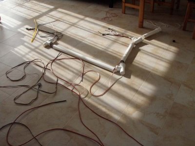
Pawel Lancucki | profile | all galleries >> Pawel Lancucki - Amateur Astronomy >> ATM corner >> My balcony observatory >> Step 5 - Cabling once again - done properly tree view | thumbnails | slideshow

Step 5 - Cabling once again - done properly

This time, I have started with purchase of wider conduit pipes - 50mm. Pipes were cut to length and dummy installed on the balcony to ensure that everything fits.

I have also checked how much cable overhand I need on each end. As per my design, the "cable-wise" distance from the end of telescope to the inside of the splitter box is just short of 5m, so I could use readily available USB and video cables of 5m length, other cables were cut to length on spot.

Nest - all cables were laid on a floor of w warm room and routed through the pipes one by one, and one section of a pipe at a time. Due to larger diameter of the pipes, no forcing of cables was needed.

After all cables were in place, I decided to run simple conductivity tests on individual wires using an universal meter. Better at this stage than to discover a broken cable while trying to connect to a CCD camera from a PC on a clear night ;-)

Next, the pipes were joined together in proper orientation.

Next, the entire cabling harness was carried outside and installed as one unit. Pipes were than tied to the observatory pier and the box using tie wraps and special clamps.

Finally, cables were routed inside the splitter box and through the mount.

Inside the splitter box, power cables were connected. I use separate 13,8V 3/5A supply for CCD camera, 13,8V 5/8A supply for the mount and dew control and 5V 3A supply for USB box (that much power is not really needed, most of the USB devices use separate supplies).

The signal cables were also connected - 3 x USB cables coming from the scope to an active HUB, one RS232 cable goes to the Robofocus unit inside the box and one to the GTO controller. There are also 4x video cables for future use (a sensitive video camera piggybacked on the scope would allow visual check of where the scope is pointing, also 1 or 2 video cameras are planned as part of the meteor / bolid monitoring system.

After all cables were connected, the inside of my splitter box looked pretty busy ;-)

Few spare cables were also routed - RS232, USB, power, video and flat gray and color cables (10 wired) for future use.

GOTO Stage 6

ss_pa224154.jpg
ss_pa224154.jpg
ss_pa224155.jpg
ss_pa224155.jpg
ss_pa224156.jpg
ss_pa224156.jpg
ss_pa224157.jpg
ss_pa224157.jpg
ss_pa224158.jpg
ss_pa224158.jpg
ss_pa224159.jpg
ss_pa224159.jpg
ss_pa224160.jpg
ss_pa224160.jpg
ss_pa224161.jpg
ss_pa224161.jpg
ss_pa224162.jpg
ss_pa224162.jpg
ss_pa234165.jpg
ss_pa234165.jpg