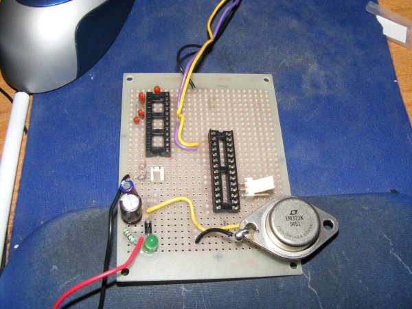
The last time, I showed a picture of my breadboard with the working servo controller circuit on it. This is going to be the permanent home of that circuit. It currently has the power circuit, the RS232 (com port) circuit and most of the programming circuit for the ATMega168 (the two white headers are where the programming board plugs in, the small black socket is the MAX232 chip, the big black socket is the ATMega168). I've tested the RS232 circuit and the power circuit and they are working fine - still need to provide power and a reset button before I can check the programming circuit.
With the change to the 3 Amp power circuit, the power circuit takes MUCH more room on the board. I think I can squeeze it in, but if I was starting over, I'd have used a bigger circuit board! I still have 5 headers left to put in!