photo sharing and upload picture albums photo forums search pictures popular photos photography help login
Pawel Lancucki | profile | all galleries >> Pawel Lancucki - Amateur Astronomy >> ATM corner >> ATM projects related to Takahashi equipment >> 2012-04 Attaching Robofocus motor to FSQ106ED micro-focuser tree view | thumbnails | slideshow

2012-04 Attaching Robofocus motor to FSQ106ED micro-focuser

After modifying my FSQ106N to accommodate 106ED focuser, I have devised arrangements to attach Robofocus motor to the FSQ106ED micro-focuser knob.

The inspiration for that come from the New Critical Focusing Zone (NCFZ) analysis. It was proved that the original CFZ calculations provided much too optimistic figure - an imaging system with detector on either end of the CFZ experienced deviation from perfect Airy image comparable to 1/4 wavefront error. As up to 1/8 to 1/10 wavefront error can be detected as slight enlargement of star images, this finding is particularly important for focusing precision of imaging systems. The NCFZ formula can be approximated with F_ratio^2 simplification - i.e. for f/5 FSQ, the NCFZ will be roughly 5^2 = 25um.

As in other similar projects of mine, I decided to attach Robofocus motor to the micro-focuer knob using a quick release system of a dedicated "cup adapter" and 3 nylon screws. The "cup adapter" has bore of ca 4,8mm and is attached directly to the Robofocus gearbox output steel shaft. I have discarded the brass collar press-fitted onto the shaft by Technical Innovations as in the past it proved to be a source of focusing errors due to slippage (in another case, the collar literally slipped of the shaft with finger pressure). The brass collar was gently cut along the axis with Dremel precision cutting disc and removed from the shaft.

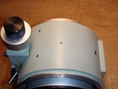
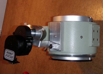
This time, I went with a different idea on how to attach motor to the scope - I have removed the original serial number plate from the focuser housing - which is held by 2 tiny M2 screws. One of the screws was replaced back and the second was replaced with long stainless steel Allen bolt, which holds 7cm long 2 x 3cm "C" profile tight to the housing. A compressible M5 nut was installed in the "C" profile.

For the motor, I have bend a short length of 20 x 2mm aluminum bar into the "Z" shape. Finally, a nickel-covered brass thumb screw is used to quickly attach / detach the motor to focuser.

Initial testing results were very promising, with measured step size around 0,9um and a very symmetrical, repeatable focusing curves under FocusMax. As usual, the proof will be in the real imaging runs, for which now I need to wait until the beginning of Autumn.
ss_p4214564.jpg
ss_p4214564.jpg
ss_p4214568.jpg
ss_p4214568.jpg
ss_p4214569.jpg
ss_p4214569.jpg
ss_p4214571.jpg
ss_p4214571.jpg
ss_p4214572.jpg
ss_p4214572.jpg
ss_p4214573.jpg
ss_p4214573.jpg
ss_p4214574.jpg
ss_p4214574.jpg
ss_p4214575.jpg
ss_p4214575.jpg
ss_p4214576.jpg
ss_p4214576.jpg
ss_p4214577.jpg
ss_p4214577.jpg
ss_p4214578.jpg
ss_p4214578.jpg