Once the three black screws are removed the screen and backing shell can be slightly lifted from the front case.
This is the most difficult part of the disassembly so take your time.
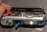
The screen flex connector must be unlocked and removed within the narrow space without straining the circuit. Separate the screen shell by only about 6mm from the front case.
From the bottom,use a long thin tool to unlock the flex circuit connector and carefully disconnect the flex connector.
Since the main board insulator covers the flex circuit lock, remove from the main board and use double stick tape to affix to the inside of the plate under the LCD.
Upon reassembly, line up all the tabs on the screen backing shell with their correct positions in the front case.
Leave about 6mm of space so the tabs just engage reinsert the flex connector in the socket and with a long tool reset the connector lock.
Finally press the two parts together until snug.