


|
|
|
|
|
|
| |
The location your charger is mounted in plays a critical role in its life span & longevity. Care should be taken to follow your manufacturers instructions of orientation, access to air, moisture or battery gas exposure.
1 - Mount the charger in a location were it can run cool and air can move around it. An engine space is often a poor location because the engines, and engine bay, remain warm long after the engine has been shut down. Many also have water heaters that can keep the temps in these small areas higher than average. While on many vessels you don't have a choice in this matter, due to space constraints, always look for a location outside the engine space before installing there. If the charger has a fan be sure to mount the inlet and outlet in areas where they will have unobstructed air flow. If necessary, or prudent for your charger, you can cut ventilation holes in lockers, and then cover the holes with pre-made ventilation grills to allow air flow. Ventilation for your charger does not have to look bad. There are many grill options available from teak to stainless steel.
2 - If your hull is a dark color it is best to avoid mounting the charger directly to the inside of the hull. Topside hull temps, in direct sun, with dark colors, can easily exceed 140F! I have one customer who's AGM's were dead every two seasons use, about 100 cycles, like clock work. He had done everything suggested by the manufacturer including installing solar for his mooring sailed boat to keep them at or near full charge. It was not until I measured the battery compartment temps at 133F, located behind the cabin settee seat back, that we figured out his failure mode. Just as heat is bad for batteries it is also bad for the charger. A cool running charger is a happy charger. If your chargers fan runs constantly it may be trying to tell you something..
3 - Battery chargers should not be mounted in a battery compartment/space despite being ignition protected. Corrosive battery gas can damage the metals in the charger and lead to shorter life or corrosive damage. All lead acid batteries, WET, GEL and AGM have the potential to vent corrosive gas. Just because your battery is a VRLA design does not mean it won't vent corrosive gas if over temped or over charged. A battery compartment is an absolute last resort location for a charger.
4 - Try to find a location that is dry and will not have the possibility of water dripping on the charger. If there's even a slight potential of water exposure a drip shield should be constructed to protect the charger. The drip shield should prevent water from damaging the charger, but also allow for proper cooling. This is not always an easy task so mounting in a known dry spot is always the best approach. Generally speaking, higher in the boat is often better than lower in the boat for a charger mounting location. Areas closer to the bilge, or with direct ambient access to the moist bilge air, tend to be more humid and corrosive environments.
5 - Try to mount the charger as close to the battery bank/banks as possible without mounting in the battery or engine compartment. Shorter wire runs mean less installation cost, less voltage drop can make for better charger performance over the long haul.
6 - The area on your vessel where the charger is mounted should be clean and free of oils, vapors or other sorts of contamination. While UL 1236/ABYC chargers are "ignition protected" it is not recommend to install them where any gas vapor can accumulate. This includes LPG, gasoline, hydrogen gas or where stored solvents could spill & leak.
DC WIRING
DC Positive & Negative:
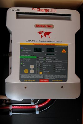
The DC wiring is a very critical part of a chargers performance. Most manufacturers want to see a max voltage drop of between 1% & 3%. Voltage drop is determined by the amperage flowing through the cable over the "round trip" length. This means you add the full length of the negative and positive wires plus the max amperage that will flow to determine to your voltage drop. This 20A charger was wired up for less than a 1% voltage drop using 6GA wire. I personally prefer as little drop as possible. Realistically I could have easily wired this with 10GA wire and been at 2.75% voltage drop but Sterling ideally wants to see less than that and I don't stock 8GA wire, so 6GA it was.
A 3% voltage drop at 14.6V is roughly 0.44A of lost voltage between the charger and battery bank. This can potentially leave you with a charging voltage at the battery of just 14.14V. With DC charging sources bigger wire is almost always better.
I very often use this voltage drop calculator: VOLTAGE DROP CALCULATOR(LINK)
Chassis Grounding:
The chassis ground wire on marine battery chargers must be sized to carry the full DC fault current of the charger and the ABYC standards require this wire to be no smaller than one size less than the DC output wires. In other words if you are using 6GA wire for a 20A charger then you'll want either 6GA or 8GA wire for the chassis grounding as well.
© All Images property of Compass Marine Inc.