


|
|
|
|
|
|
| Stephen Gerow | profile | all galleries >> Galleries >> Kirk Headers | tree view | thumbnails | slideshow |
| previous page | pages 1 2 3 ALL | next page |
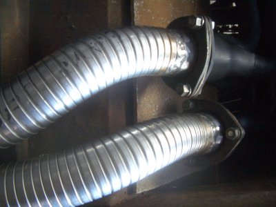 FlexKinkInstalled.JPG |
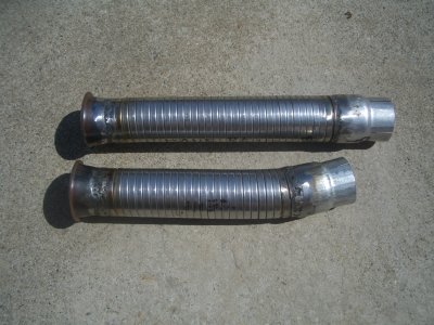 StraigtenedFlexTubes.JPG |
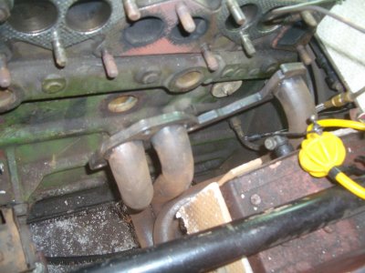
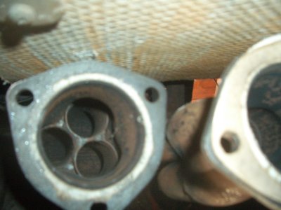
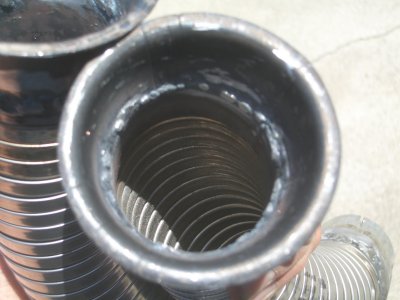 ViewDownThroat.JPG |
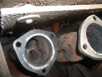
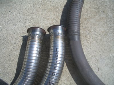 CompareWithOldBraze.JPG |
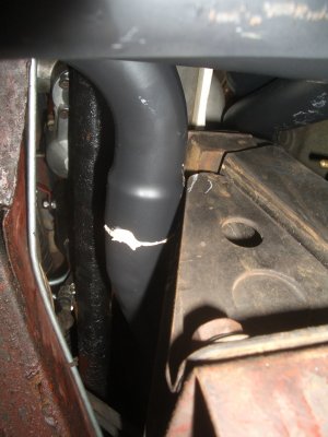
 FuelLineHeatShieldSoft1.JPG |
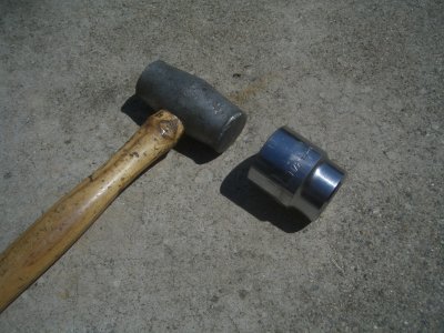 HammerSwageTool.JPG |
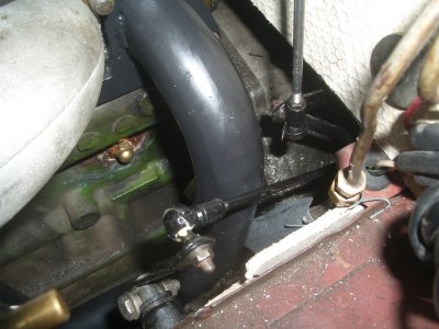
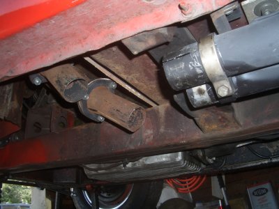
 HeaderMotorMount1.JPG |
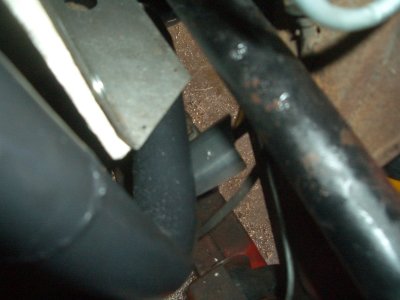
 HeatShieldOilLine1.JPG |
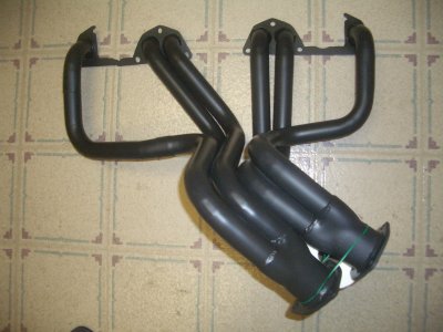 HeadersBlackCoated |
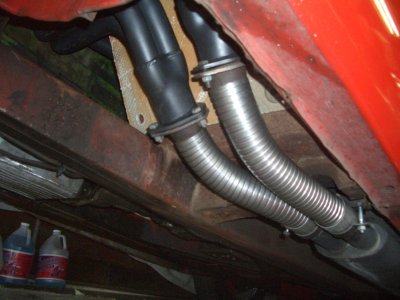
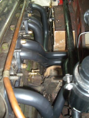
 FlexInstalledHoriz2.JPG |
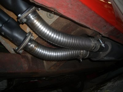
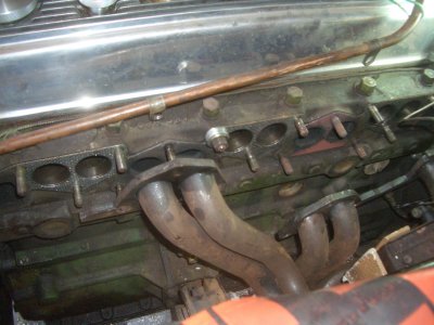
 Flex connections from front |
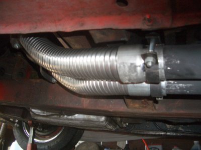 Rear connectors |
 FlexWConnectors2.JPG |
 AssembledFlexConnDarkHoriz.JPG |
 Front |
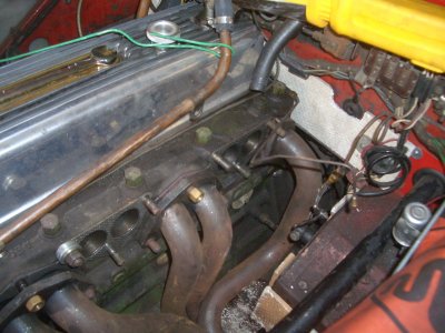
 side rear |
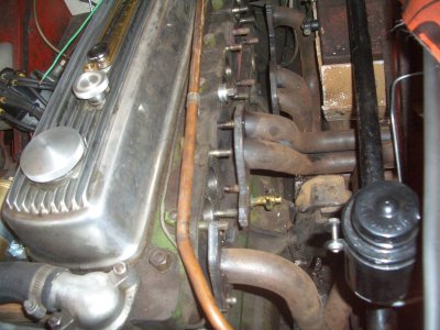
 side front |
 View from bottom-fender |
 Collectors under floorboards |
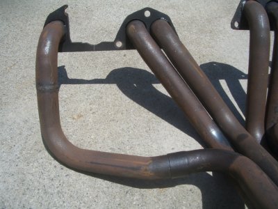
 Kirk Headers Full |
 Partial Slot |
 Slipjoint #1 Cylinder tube |
 Note Raised mating surface |
 Installation: Step1/5: lower inside fender flange bent for clearance |
 Step 2/5: Insert rear section from top, leave loose |
 Step 3/5: insert 2/3 cyls section from bottom, leave loose |
 Step 4/5: attach cyl 1 section, position all on studs at same time |
 Step 5/5: tighten all nuts evenly |
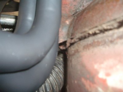
 collectors tight against footwell floor |
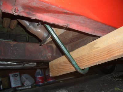 adjust collectors downward crowbar bending tool |
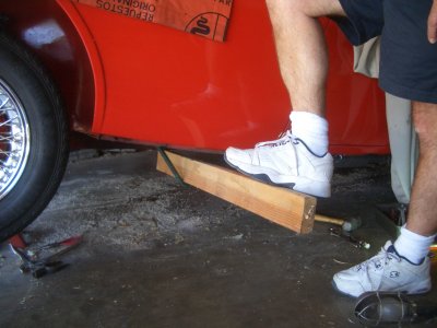 method for adjusting collectors downward |
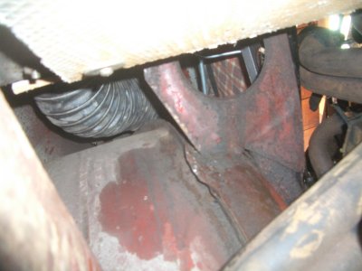
 adjusted collectors with clearance |
 adjusted collectors with stubs |
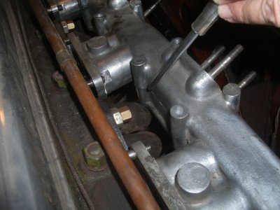 pointing to interference with stock intake (won't be used) |
| previous page | pages 1 2 3 ALL | next page |
| comment | share |