


|
|
|
|
|
|
| Rolf Olsen | profile | all galleries >> Astrophotography >> 10 inch Serrurier truss Newtonian | tree view | thumbnails | slideshow |

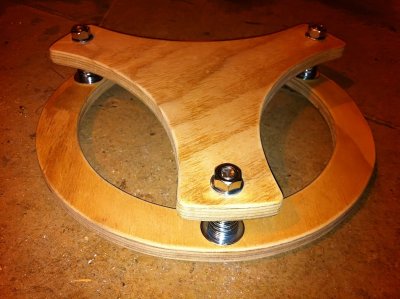
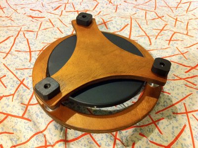
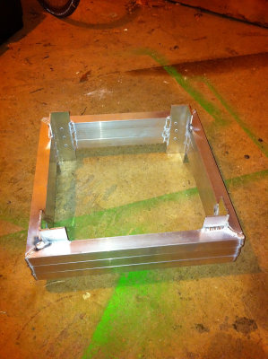 Central brace |
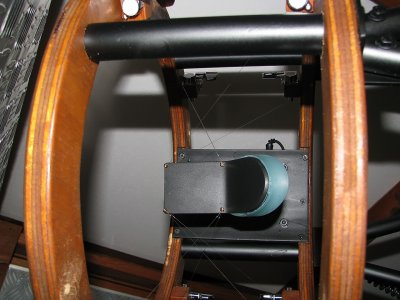
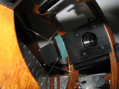
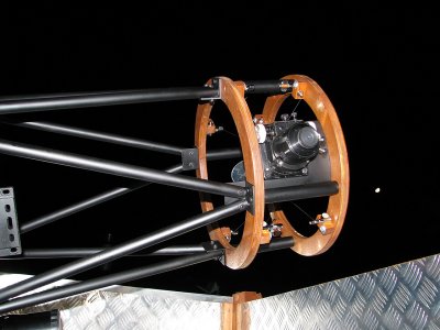
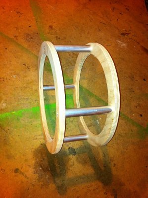 Secondary cage |
 Secondary cage |
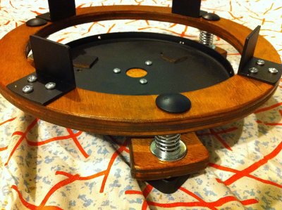
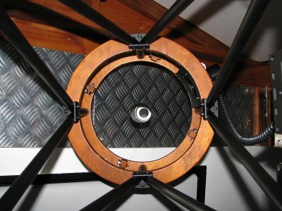
 Mirror cell top |
 Mirror cell bottom |
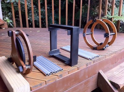
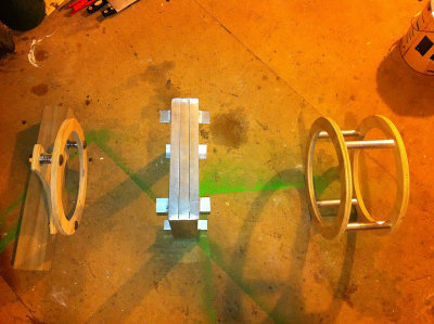 The parts laid out |
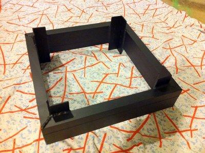 Central brace painted |
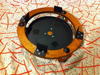 Mirror cell painted and with truss connectors |
 Finished mirror cell bottom |
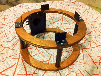
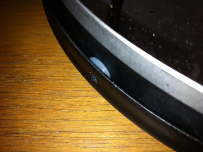
 Mirror cell close up |
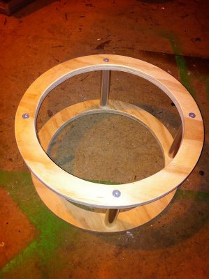
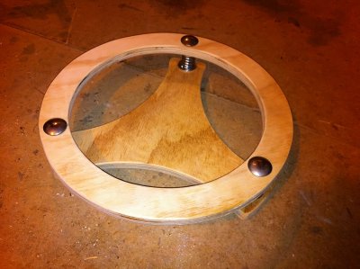
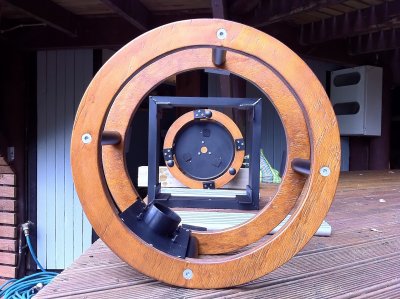
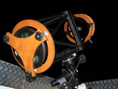
 Finished secondary cage |
 Finished secondary cage |
 Truss tubes ready to be installed |
 All lined up |
 First truss triangle |
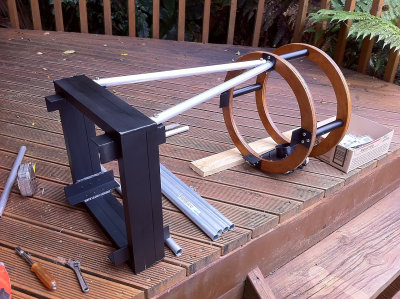
 The completed upper half |
 Trusses finished |
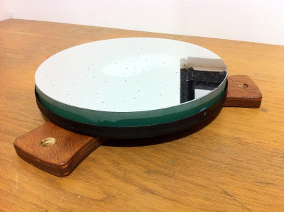 Mirror attached to the cell bottom |
 Mirror siliconed in place |
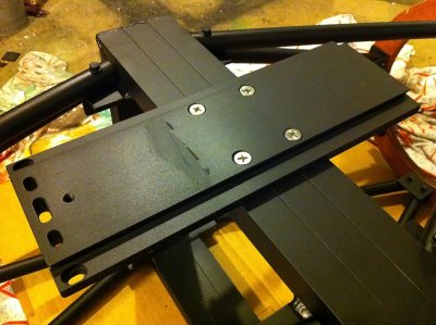 Dovetail plate attached to the central brace |
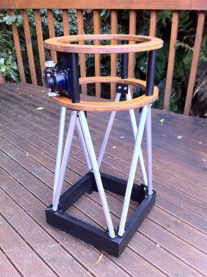
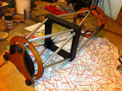
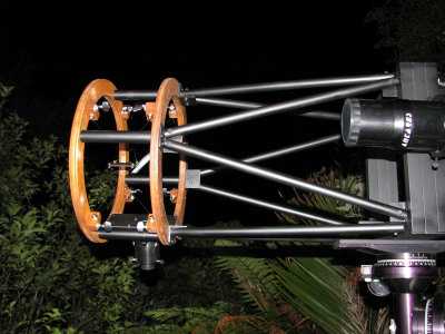
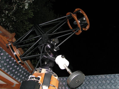 The finished OTA! |
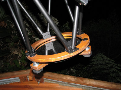
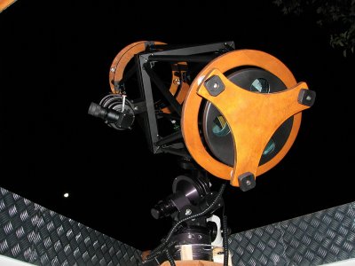
 Bottom view of the OTA |
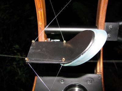
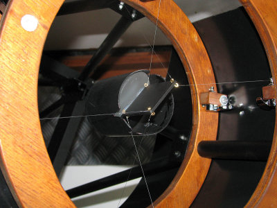
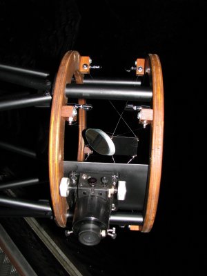 Secondary cage with wire spider |
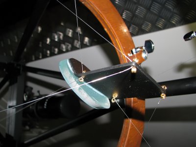 Detail of wire spider |
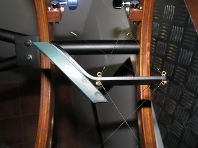 Detail of wire spider |
 Detail of wire spider |
 Detail of wire spider |
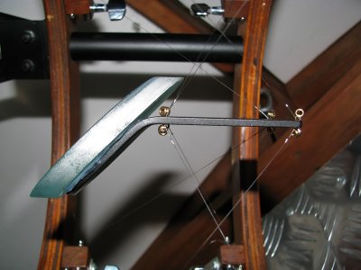 Detail of wire spider |
 Detail of wire spider |
 Detail of wire spider |
 Wires are nearly invisible |
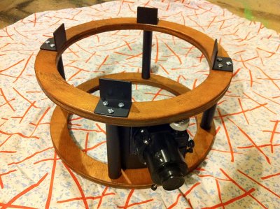
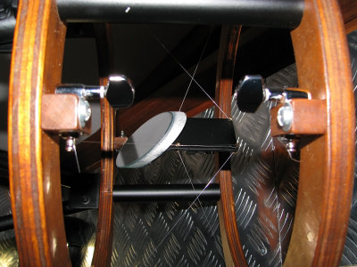
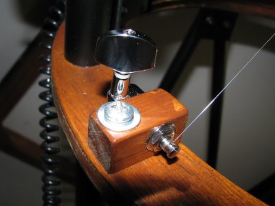 Machine head in pivot mount |
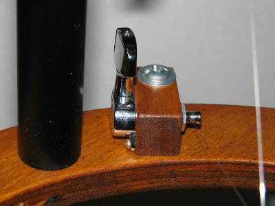 Machine head in pivot mount |
 The (dusty) mirror |
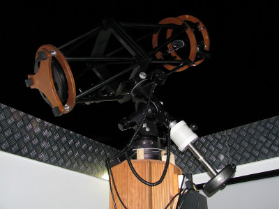
 The upper half |
 Ready to use! |
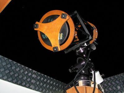 The completed OTA |
 A view of the Moon... |
 The completed OTA |
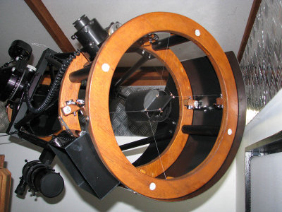
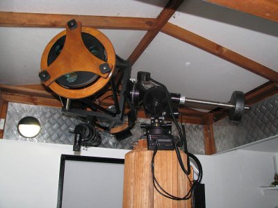 OTA parked horisontally in the observatory |
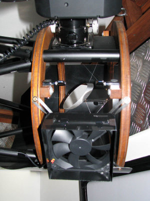 Secondary cage details |
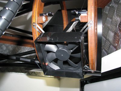 120mm fan to prevent dew on the secondary |
 Larger secondary (70mm) installed April 2012 |
 Larger secondary (70mm) installed April 2012 |
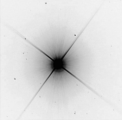 Betelgeuse 53x6.5s with old OTA |
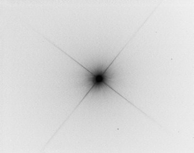 Spica 20x5.5s with new OTA and wire spider |
 Jewel Box cluster with new OTA, practically no diffraction spikes! |
| comment | share |
| Best Annabelle Dollhouse From Kidkraft for Little Ones | 25-Dec-2017 16:29 | |
| SmartmilToys.com | 12-Nov-2016 13:05 | |
| John Ailshire | 26-Mar-2014 06:16 | |
| mark | 26-Jun-2012 12:27 | |
| Michael, from Romania | 06-Apr-2012 09:23 | |
| Ram�n from El Salvador | 24-Mar-2012 23:41 | |
| Guest | 18-Jan-2012 02:34 | |
| Ted Meyer | 27-Nov-2011 19:16 | |
| Rolf Olsen | 06-Nov-2011 09:58 | |
| Pavol | 01-Nov-2011 23:41 | |
| Lennart Waara | 22-May-2011 11:22 | |