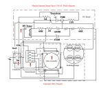
Electrical schematic drawn from a dissasembled Maxxum 1200 AF Macro Ringflash.
As you can see, it is really not a ringflash but four seperate tubes which can be controlled individually.
The tubes are switched on and off by switching the high voltage "trigger" circuit to each tube. The tubes are wired parallel and held at high potential whenever the flash is plugged into the controller.
A TTL level signal from the flash (originating from the camera) sends a pulse to the High Voltage board which converts it to high voltage with the transformer triggering the flash.
Thyristor circuitry within the controller unit modulate the length of the flash depending on what is calculated for exposure during preflash.
It should be easy to make a flash that plugs into the controller as long as it has a similar HV circuit for triggering. The HV board circuitry is similar to many trigger circuits used in low power flashes.