A hidden Screw ?
Underneath the Mode Dial you will
find another screw that holds the
Top Cover.
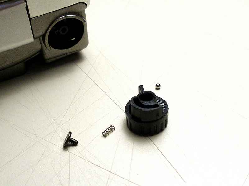
Do Not Remove
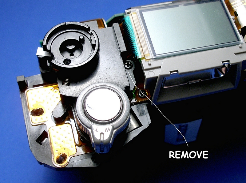
Don't do as I did by removing this
Diopter Adjusting Knob. The camera
can be removed from the rear case
by lifting up on the opposite end
and rocking it out. This is a bear to
reassemble. The little spring fits
down into a hole, the ball is placed
on the end of the spring, then the Knob
is placed over and retained with the screw.
That little ball has a mind of its own.
Jumps off the spring and hides. The last time
it hid for good and I never did find it.
So as a replacement, in my junk drawer was
a tiny ball bearing from my model building
days. I took it apart and found the balls
were the same size.
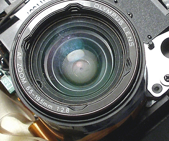
Close-up of jammed lens
If you look close you can see the opening for
the f stop. This shot is with the camera covers off.
Not a good picture, but
I am not going to take this camera apart again for
anotherpicture. Anyway down in the recess
(maybe 3/8 inch deep)is a place where you have to
remove/reassemble a very tiny screw. My old
Tool Design/Toolmaker past helped here. I used a
piece of shrink tube "shrunk" about the head of
the screw and the shank of the Phillip's Jewelers
screwdriver.Worked like a charm.
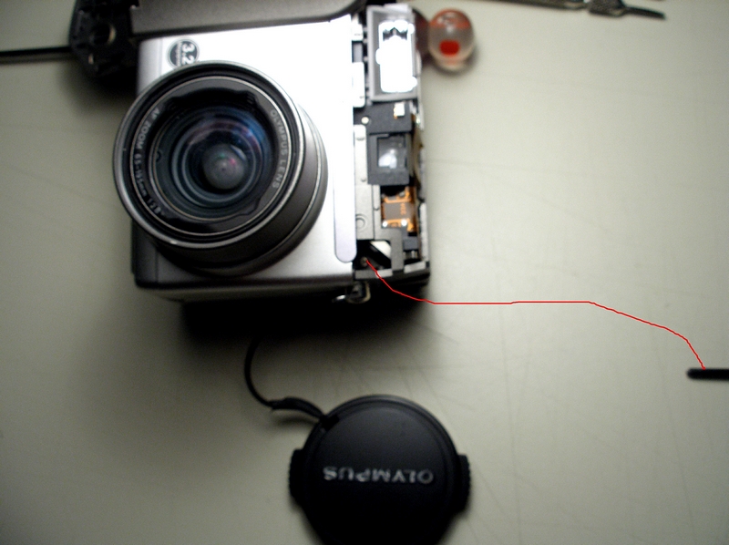
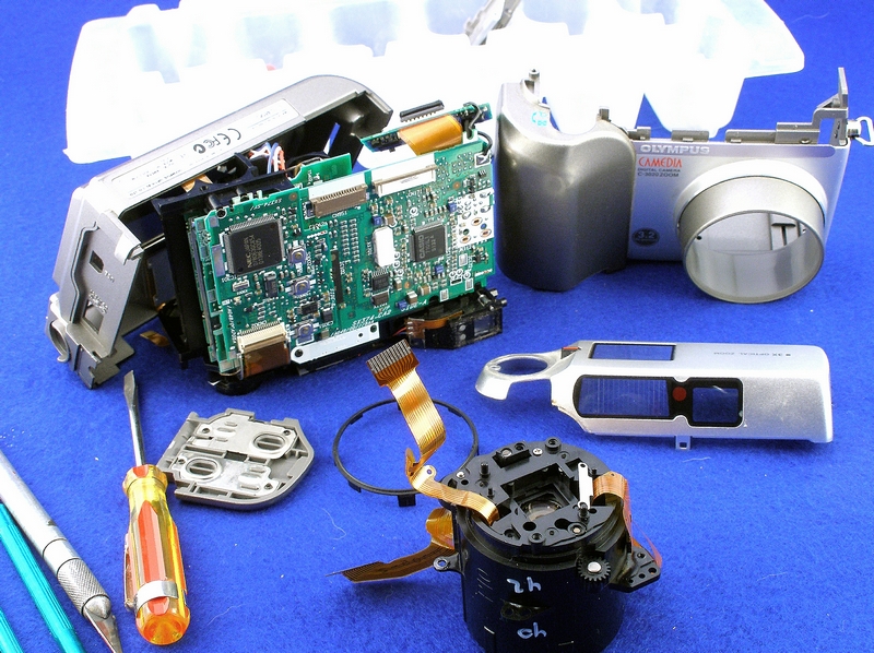
C-3020z with the covers off.
Now here is where you can get a shock.
This little camera has bit me twice.
Note in the area where you see the color wires,
This is the area for the capacitor for the Flash.
KEEP your fingers off this area. Not a pleasant feeling.
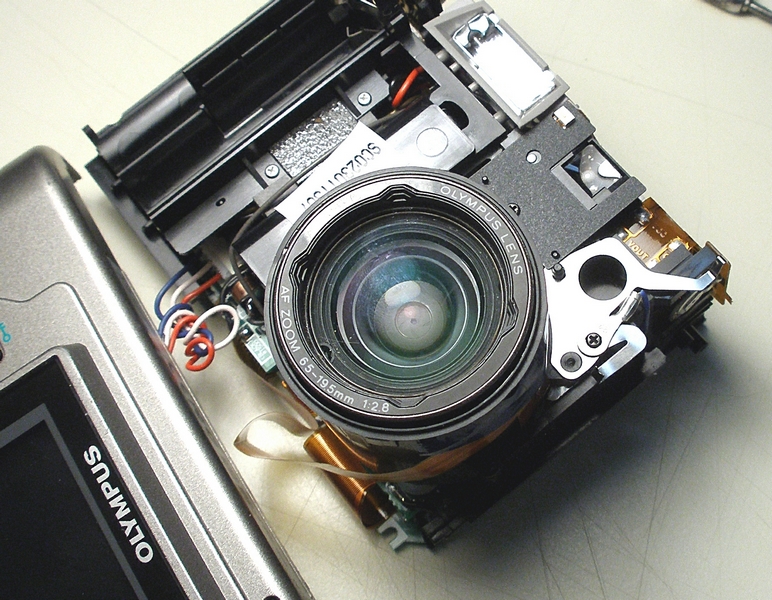
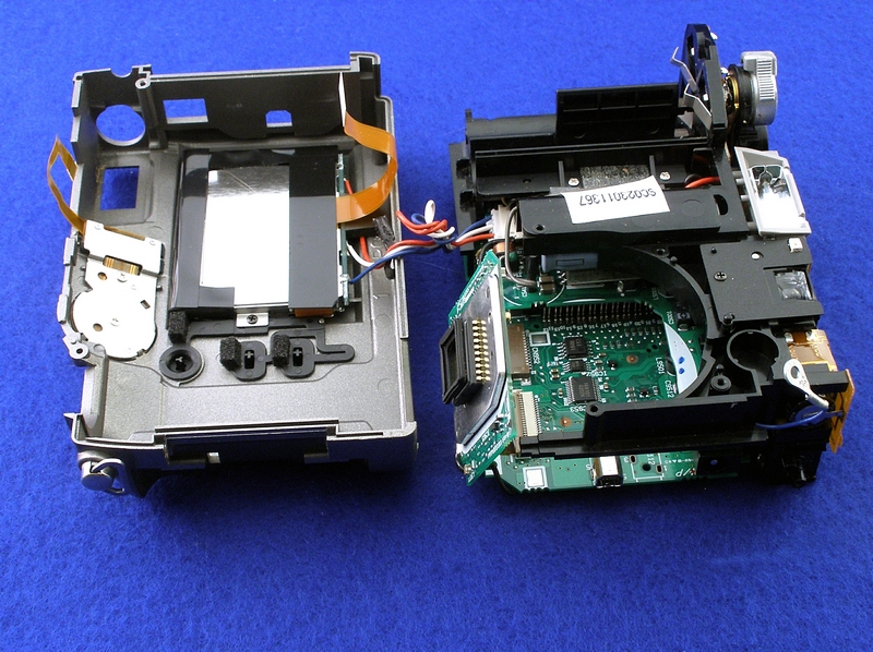
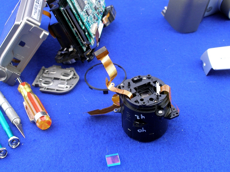
Another view of the dis-assembly
This shot is when I had tore down the
entire camera. Note the lens housing
sitting in the front.
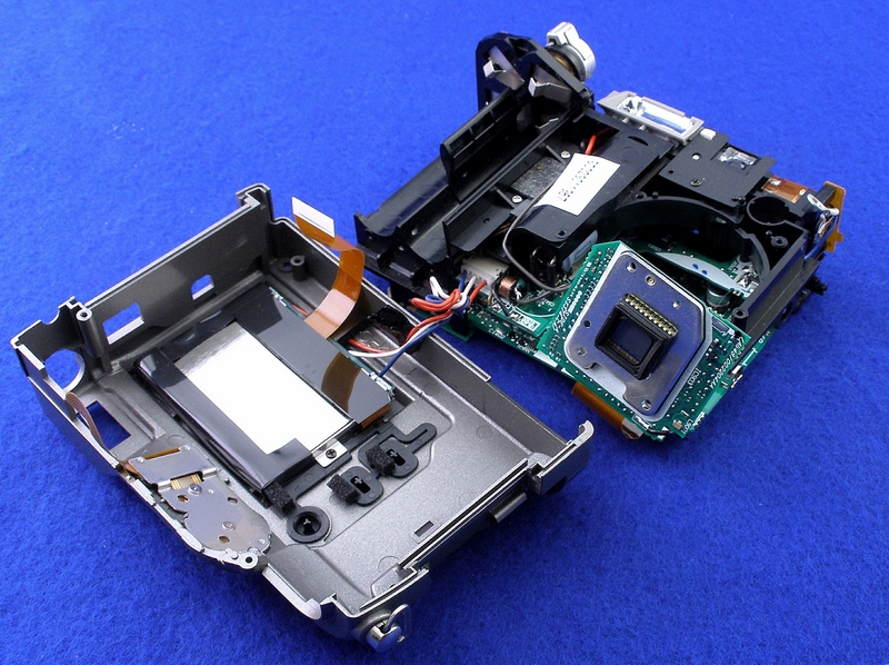
Almost ready to mount the Sensor Circuit Board.
This Sensor Circuit board is mounted to the rear
of the Lens Barrel assembly. Then the two halves
of the lens barrel will be held together.
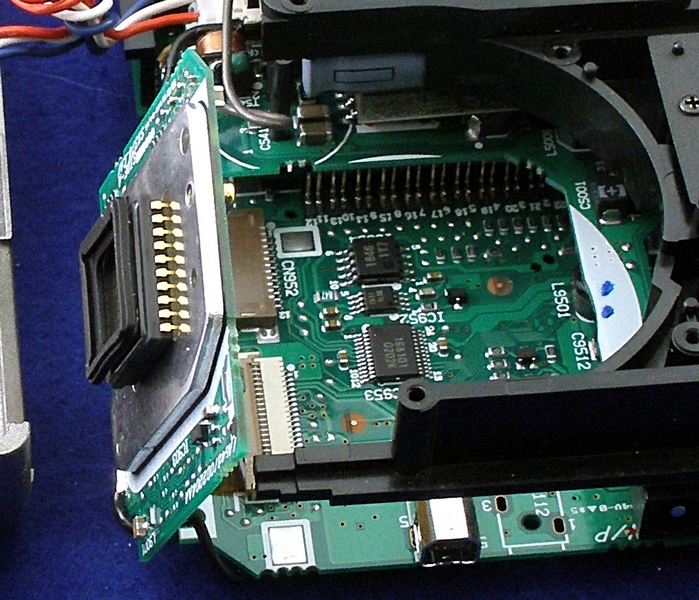
Another view of the Sensor Circuit Board
This view to show the sensor mounted
to the circuit board.
Another View of the Sensor Circuit Board.
After the Sensor is mounted to the rear of the
lens barrel assembly, this composite assembly
will be mounted back into the camera body. The
camera back will be rotated for assembly.
Note! at the top of the camera body. You can
see right under the knob, part of the battery
case. The other half is on front part of the case.
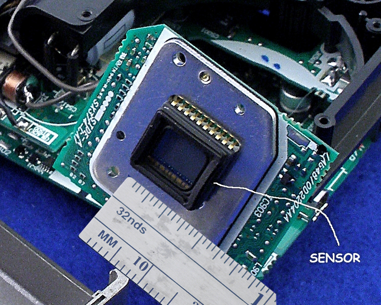
A close up of the Sensor.
I find it very mind boggling after looking at
the size of the sensor, that we get such clear
pictures at a very much expanded size.
Lens Housing removed from camera.
Note!
The little glass part in the foreground
is the IR filter. Without it and a piece
of plain glass in its place I would have
a dedicated IR camera.
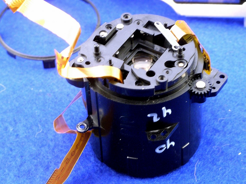
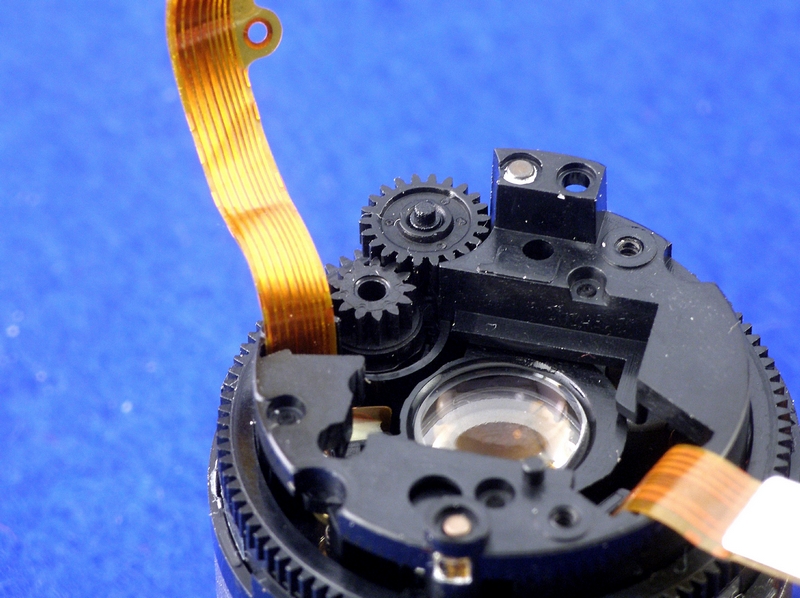
Lens Housing with the Sensor removed.
The little gear on the right hand
side of the housing is jammed. This
gear meshes with the gear on the
camera motor.
Note! the IR filter fits into the
Rectangular opening on the back of
the lens housing and is held in place
with the Sensor and its circuit board.
Close-up of the Lens Housing
As a result of this cameras fall, the little
gear will not turn at all.
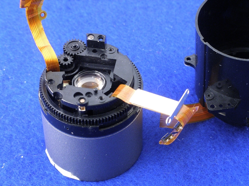
Lens Barrel removed from the Lens Housing
Note! The small gears.
This is a two part housing.
A top and a bottom. The Sensor
circuit board assembly holds
the two halves together.
Another shot of the small Gears
Just to the right/top of the cable you will see
one of the two small spider gear sets shown in
a following picture. They are stacked one on top
of the other and I think they control the aperture.
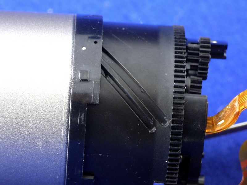
Barrel slots for moving Lens
When the silver part is in the camera it is fixed.
Turning the Bull Gear via the motor caused the
lens to move back and forth.
This is what was jammed prior to my taking it apart.
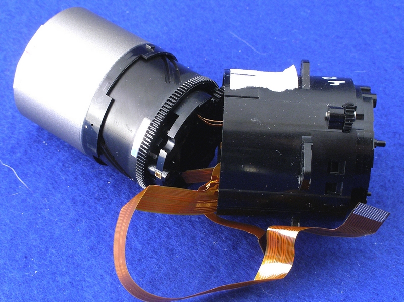
Lens Barrel and Lens Housing
Having a problem with re-assembly.
The two halves must mate together
and the two cables are routed thru
the case.
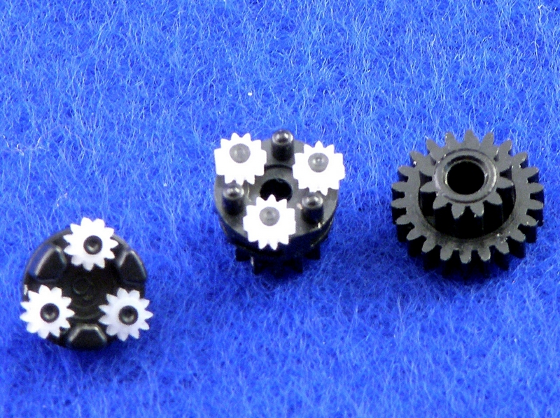
Some of the Small Gears inside the Lens Barrel
Notice the odd shape on the middle set.
When assembled into the lens barrel
they adjust the aperature?
Hope the odd shape is on purpose and I
wonder if their position is critical.
Well if the camera starts up after I
reassemble I guess I will find out.
Does anybody still wonder why cameras cost so much?
21-FEB-2007
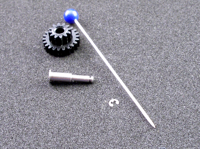
Gear; Axel Shaft and Retaining Clip. ( Straight pin for size reference)
See the next picture. This is why I have up till
now, been unable to reassemble the two halves
of the Lens Barrel. Finaly found a cover access
plate that was glued to the outside of the case.
These parts were removed and the two halves
of the unit slid together.
Going to be a job to get that little clip
back on. Hope I don't drop it.
21-FEB-2007
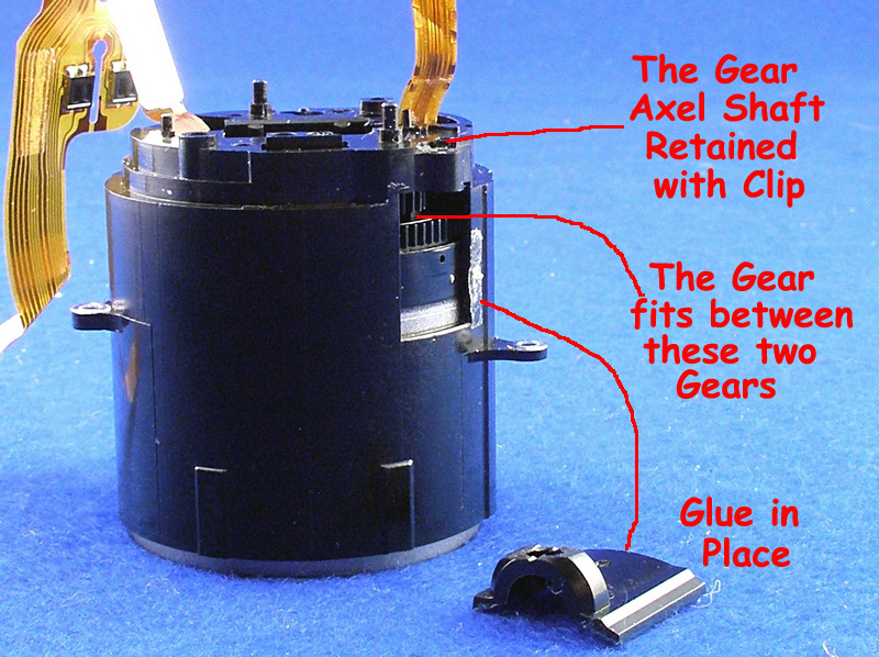
Lens Housing almost back together.
After removing the access plate and finding the
gear inside.This gear has been the reason why I
could not align all the gears and pins to reassemble
the lens housing assembly.If you notice this gear
must fit between the two gears shown.After
repeated tries I found that this gear had to fit
between one that was on the top half and another
on the bottom half.I took an eye loop and found
that there was a side cover glued to the outside
of the lens housing. I took this off and removed
the very tiny clip and then the axel and gear. The
housing slid right back together.
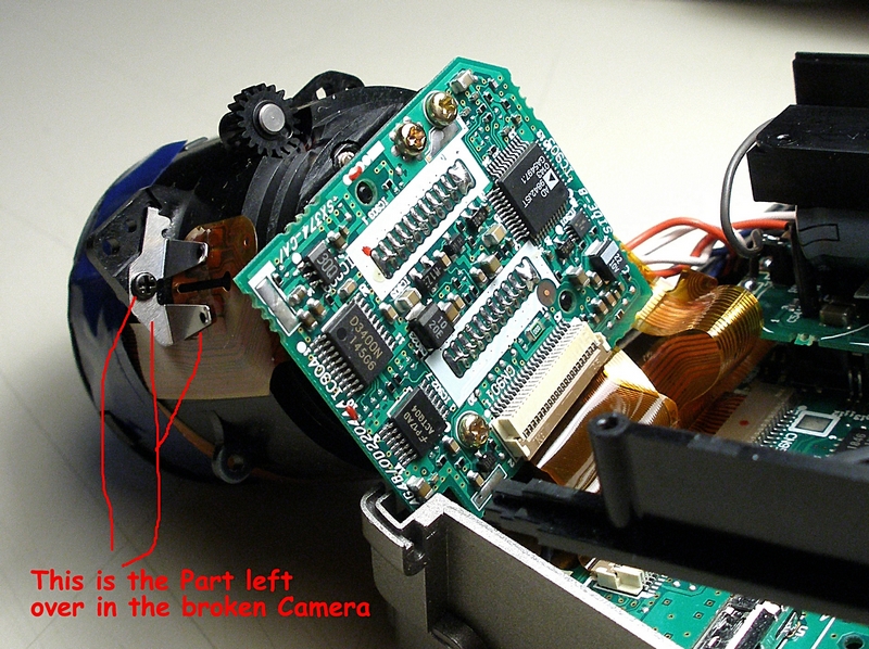
This piece was left over
When the camera was mostly together, I had this
silver color clip and a screw left over. I thought
I had taken pictures of all items as I went during
the tear down.Could not find a picture of this part,
so I took my good working c-32020z apart looking
for where this part went.Problem,this resulted in
the fact that I now had two cameras to put back
together.The good c-3020z is now back together
and operates very well.
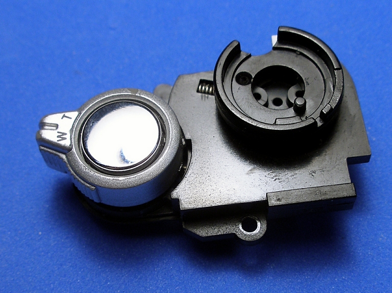
MODE DIAL/ ZOOM LEVER/ SHUTTER BUTTON
To accomplish this repair, you must
remove the top and front covers.
I replaced this unit as it was very
jerky on the zoom and the shutter
button would stick causing the Flash
to not fire correctly. There is only
one screw to remove.
MODE DIAL/ZOOM/SHUTTER BUTTON ASB'Y
It is held by one screw. See previous picture.
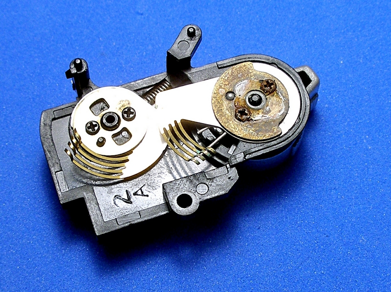
Bottom View- MODE DIAL/ZOOM/SHUTTER BUTTON