


|
|
|
|
|
|
| Neil Rothschild | profile | all galleries >> 1985 RX-7 GSL-SE >> Air/Fuel Meter | tree view | thumbnails | slideshow |
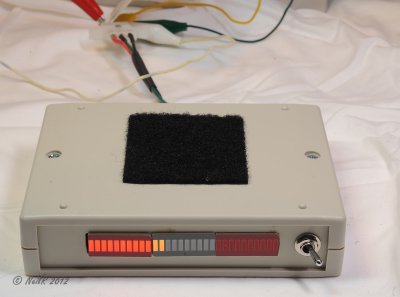
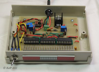
 DSCN_260686.JPG |
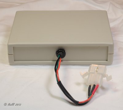
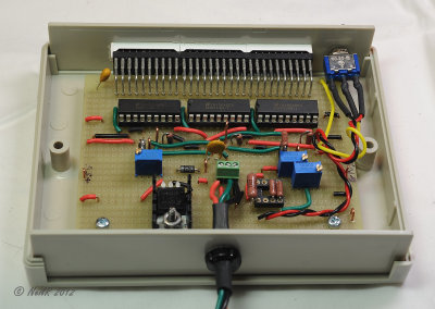
 DSCN_260691.JPG |
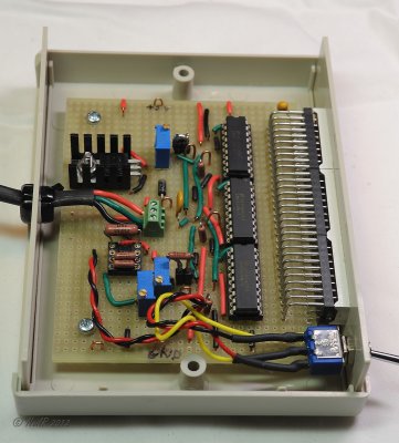
 DSCN_260698.JPG |
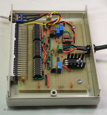
 DSCN_260703.JPG |
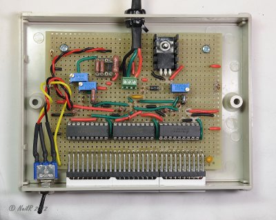
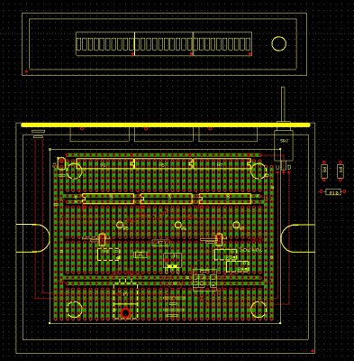 Board Layout |
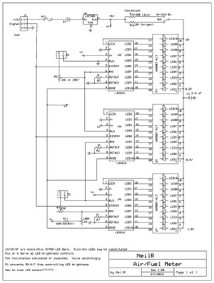 Schematic |
 DSCN_260705.JPG |
 DSCN_260707.JPG |
 DSCN_260717.JPG |
 DSCN_260720.JPG |
 DSCN_260721.JPG |
 DSCN_260722.JPG |
 DSCN_260724.JPG |
| comment | share |