11-MAR-2009
Pinhole
This tank bottom is vee-shaped thus any debris or crud winds up in the vee. The tank bed was very well designed and the vee is suspended in air on all sides so no moisture was in contact with the tank.
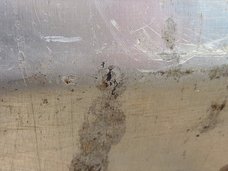
When we cut the tank open I sifted thought the dead organisms and found a chunk of dissimilar metal right over the hole. It seemed to possibly be a piece of stainless steel that had somehow fallen into the tank somewhere along the way, possibly during a sending unit change out?
I suspect that this piece of errant metal was the cause of the pin hole. There were no other signs of corrosion despite this being a 31 year old aluminum tank. Canadian Sailcraft did a very good job designing & engineering the fuel tank & beds.
11-MAR-2009
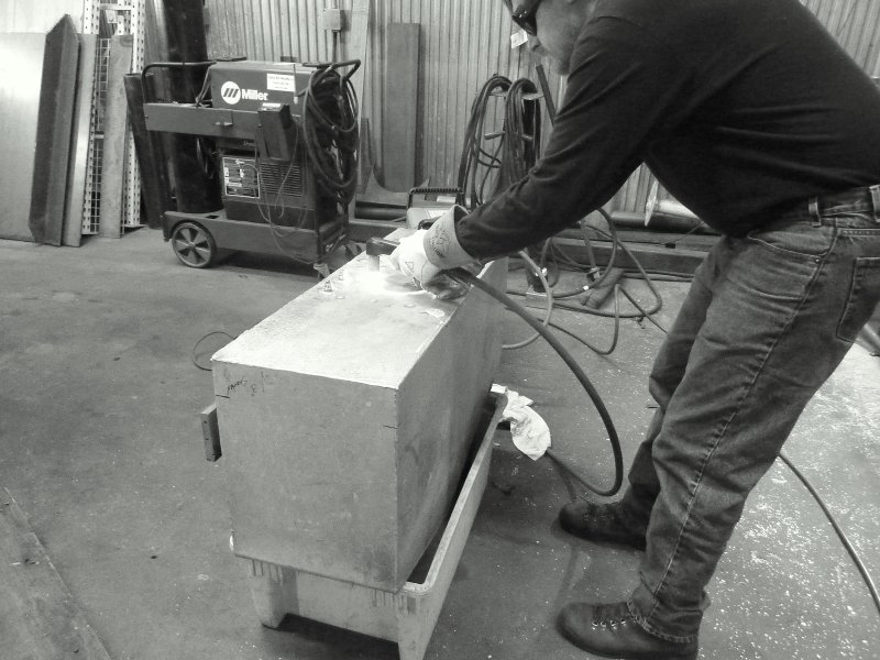
Removing The Engine
Like anything in life nothing lasts forever, including impossible to access fuel tanks. This tank was on a CS-36T and ran port to starboard under the cockpit sole behind the engine.
At first I was clearly delusional and thought it may come out through the port lazarette, but I was sorely mistaken.
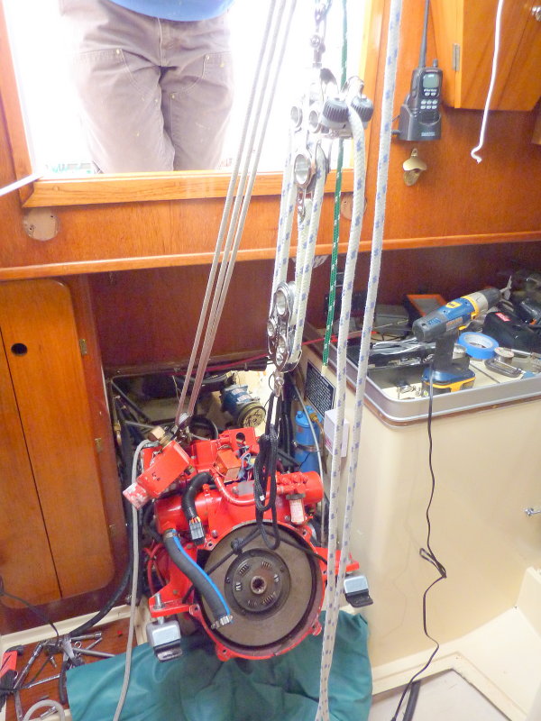
This photo shows the first step in this project, removing the engine. for removal I enlisted my main sheet, an old boom vang and a 4X4 across the companionway. Once everything was disconnected the engine came out quite easily. I had a buddy there just in case but this can be done solo on this boat.
11-MAR-2009
Placing Engine In Galley
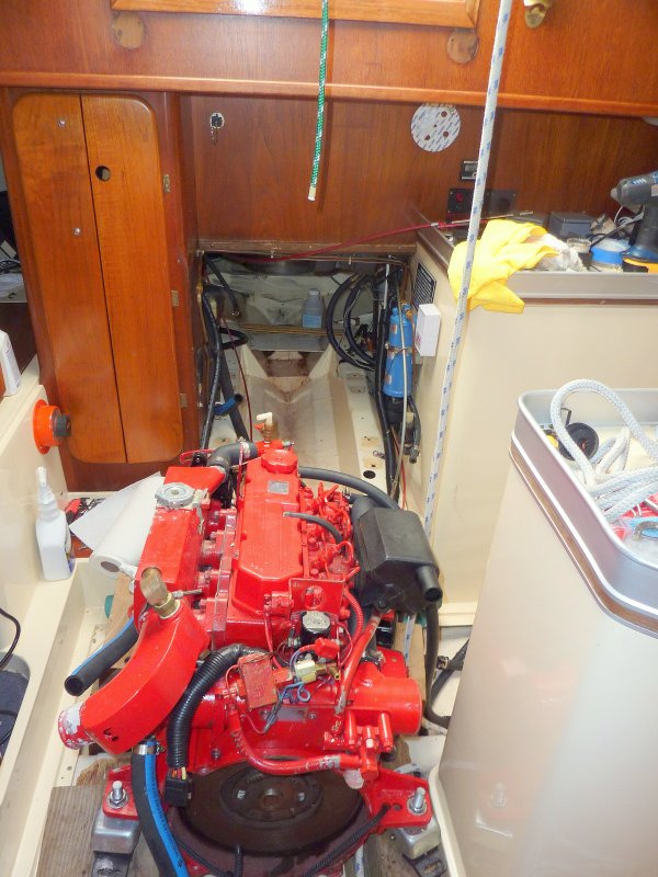
To bring the engine into the galley I had first removed the cabin sole to prevent damaging it. I then collected some boat yard blocks and gently set the engine down on them and she sat ther while the new tank was fabricated.
In this photo the fuel tank has already been removed.
11-MAR-2009
Tank Layout
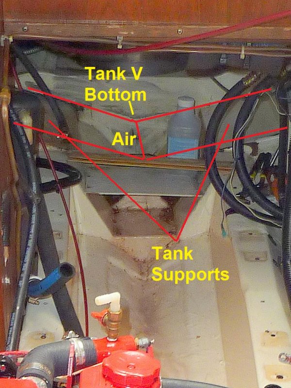
Using MS Paint I have illustrated, rather crudely, where the vee in the tank was. As you can see it was not in contact with anything and it's highly unlikely that the pin hole started from the outside, as usually happens.
11-MAR-2009
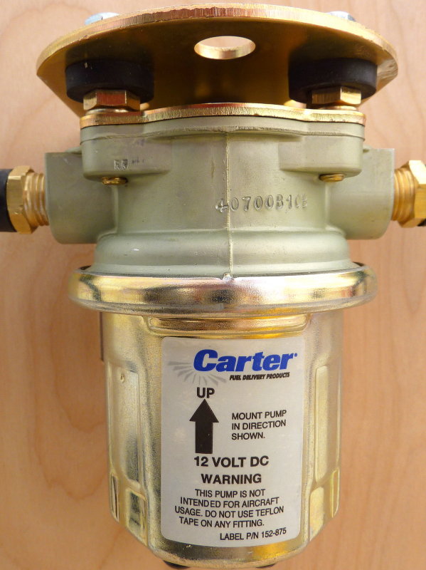
Fuel Polishing Pump
The first step in replacing any fuel tank is to remove all the old fuel. Seeing as I was planning on adding a dedicated fuel polishing system I used my new fuel polishing system pump. I made a home made stand out of some plywood and mounted the pump to it. I then connected some fuel hose a shut off valve, a 12v pigtail and a switch. I simply transferred the fuel in 5 gallon cans, through the Racor filter and I burned it in my homes oil boiler.
11-MAR-2009
Cutting Open The 31 Year Old Tank
This tank had been running biocides since new and Soltron / Startron for the last 15+ years. Because of this I wanted to see how well it kept my tank clean but at 31 years old I was doubtful. Not one to believe in snake oils I chose to cut the tank open.
11-MAR-2009
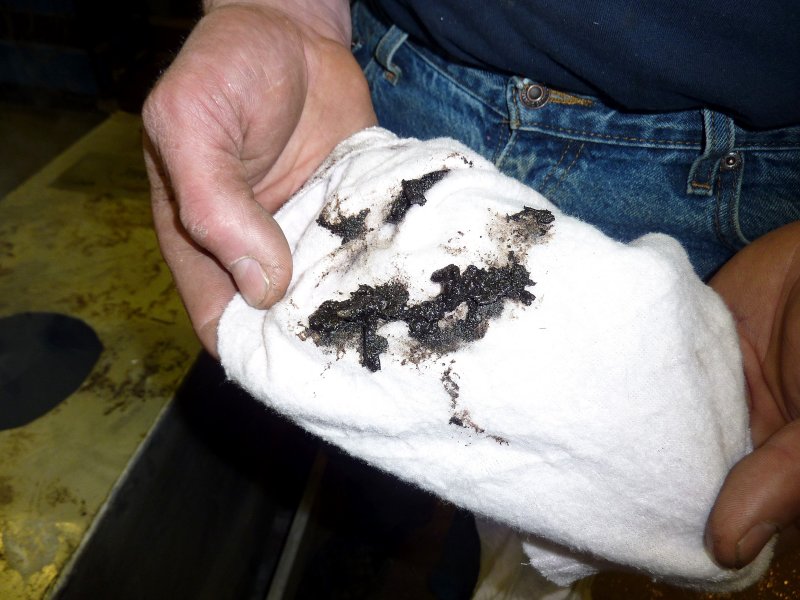
Tank Wall Sludge
With a hole cut we simply took a clean rag and blindly wiped an inner wall of the tank. NOT clean!!
11-MAR-2009
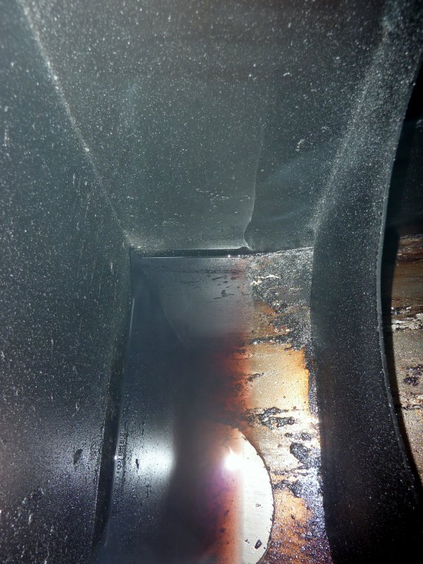
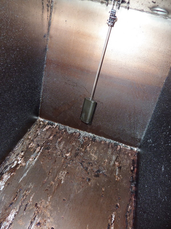
Interior View
This view is looking down into the hole cut in the tank you can see the piece of metal that fell into the tank and a baffle and also a LOT of tank grunge and grime. Remember, this boat used Soltron well before it was marketed in the US as Startron, and it had been in use religiously for the last 15+ years, yet this is what the interior looked like. It should also be noted that this was after TWO treatments Startron Enzyme Formula Diesel Fuel Tank Cleaner. Fuel tank "cleaner"? Really? Not in my experience... Oh and this tank had also been "professionally" polished by a dock side fuel polishing outfit. Polished? Really?
11-MAR-2009
More Sludge
Here's a view off towards the sending unit. No wonder the gauge was not very accurate. Doh'
11-MAR-2009
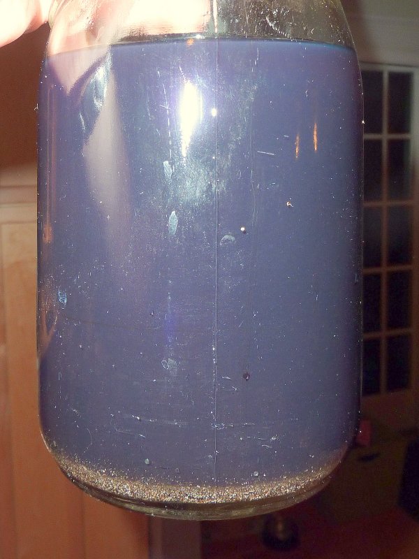
Last Few Ounces
Having never been a huge believer in the tank condensation theories that are bantered around, I wanted to see for myself how much water was actually in the absolute bottom of my tank. The answer was nada, zilch & nothing. Those gray flakes are from the plasma cutter and the fuel looked bad but still no water separated out at all. I found it rather interesting that after 31 years I found absolutely no water in this fuel tank. Perhaps the fuel treatments really do work for something..? The previous owner never even topped it off in the winter, and I drain it, but still the original pick up tube was 1.4" off the dead bottom of the tank so you never get it all. I will continue to change the deck fill o-rings, multiple times per year, as it does seem to work well..
11-MAR-2009
Aluminum Tank Fittings
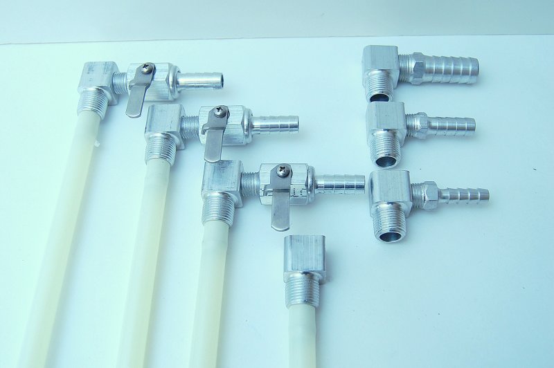
As an ABYC member I tried to build my tank to the letter of the law/standard. This meant no mixing of copper alloys and the aluminum tank as many manufacturers did and still do.
So, where the heck do I find aluminum tank fittings? I asked a friend at Morris Yachts where they got their fittings and he sent me to Luther's Welding in Bristol, RI 401-253-5550. Sure enough they had aluminum tank fittings, and shipped out exactly what I ordered. The prices were also very reasonable. Great folks to deal with.
11-MAR-2009
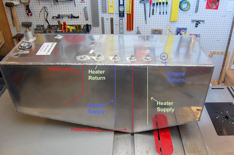
Tank Tapping Layout
I designed this tank with multiple tappings and two baffles. There is a supply/return for the engine, supply/return for a diesel fired cabin heater and a supply/return for a dedicated fuel polishing system. I did not install tank clean out ports because access to the top of the tank is extremely limited. I will eventually remove it and install clean out ports but that is likely 10-15 years out, if at all, with this polishing system. I have a friend with a very high quality scope camera that we can inspect the tank cleanliness with in the mean time to assess any need for physical cleaning.
When designing for a fuel polishing system I definitely wanted to get my polishing pick up directly over the deepest part of the tank in order scrub/polish every last little bit of the fuel. This pick up tube is 1/8" off the dead bottom of the tank and directly over the V where any crud/bugs/algae or other junk would naturally wind up.
In order to avoid foaming with a high flow polishing system the return for the polishing system is also returned via a dip tube. Returning the fuel below the level of the fuel prevents and or greatly minimizes the potential for fuel foaming. If you click the photo and make it larger you can see a drawing of the pickup or dip tubes and the supply/return tapping locations.
*******CLICK BELOW FOR PAGE 2*******