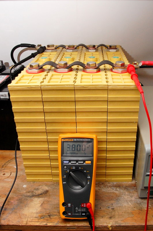
Balancing Parallel Cells To 3.800 VPC
This is why top balancing needs to be closely monitored. Like equalizing flooded batteries you simply DO NOT leave them unattended. Once the cells hit 3.800 VPC you will need to adjust the power supply very carefully so it does not overshoot 3.800VPC. While these Mastech power supplies are reasonably priced they are rather sloppy to set voltage with because they lack a dedciated voltage sensing circuit. Power supplies such as those from BK Precision etc. use a dedicated voltage sensing circuit for accurate voltage settings.
Watch the DVM NOT the power supply display. Allow the voltage to rise to 3.8000V (for Winston cells only!) and hold the cells at 3.800VPC for about 15-20 minutes once you get there. Remember trust the DVM NOT the power supply.Some folks say you can stop once you hit 3.800 VPC but I like to let the current taper a bit and 15-20 minutes is plenty, once you hit the top balance voltage. Other manufacturers, of prismatic cells, have considerably lower maximum balancing voltages such as 3.65VPC. Once the current has tapered at 3.8V for 20 minutes or so I then dropped the voltage to 3.65V and let the current go to 0A.
If you wire in parallel, hold voltage steady then allow the current to taper to flickering between 0.0A and 0.1A the parallel pack is now balanced and can be disconnected. Despite doing this with my own bank, I would not advise top balancing at 3.800V but rather somewhere closer to 3.65V for a fractional C bank. I did not feel comfortable about holding the cells at 3.800V for very long so I dropped back to 3.65V.
After you do this disconnect the charge source you can continue to let them sit, in parallel, for as long as you want, after discharging them to a storage SOC of 50-60% SOC.
Once I have attained my peak top balance voltage I then let them drop to a lower peak voltage, such as 3.65V on Winston cells, or 3.55V on CALB and I then allow the power supply to take the batteries to 100% full with the power supply bouncing between 0.0A and 0.1A. This actually puts the cells in balance at that voltage. At this point you can un-wire the cells and they are balanced..
EDIT: I recently conducted an experiment on my test cells that pitted a "balancing BMS" against a 3.65V parallel top balance to 0.00A - 0.1A on the power supply. Holding the cells at 3.65V (CALB cells) the top balance in parallel actually balanced the cells in just under 3 hours. Using the "balancing BMS" after more than 7 hours at shunting / balancing voltages the cells were still not "balanced"..... Food for thought!
Please keep an infrared thermometer on hand and closely monitor cell temps. Hit all the cells at the same spot, when checking on the cells, to track any changes or anomaly's. They should ideally remain below 80-85F, these did.
Further Thoughts: After playing with multiple brands of prismatic cells for almost 4 years now it has become apparent that there is pretty much zero difference between these cells in terms of upper knee voltages. With that in mind I would strongly suggest there is NO NEED to top balance Winston cells, for fractional "C" use, beyond 3.65V per cell.
Bench Top Power Supply
As I mentioned earlier I am a believer that if venturing into DIY LiFePO4 it should be done as a SYSTEM. Part of that system should include funds for a bench top power supply. In my opinion this tool should be a pre-requisite for DIY LFP.. Can you make do without? Sure, and I am certain Bode Miller could ski with only one leg, but why..? In the whole scheme of things they are inexpensive and they have multiple uses not just for charging or top balancing LFP.
Two of the bench top power supplies I use are made by Mastech, specifically the Mastech EX series. I own a 3030EX and a 3050EX. These are not the fanciest or the most expensive power supplies, and voltage setting is tedious due to the lack of a voltage sensing circuit, but they work and they work pretty well especially for the price.
Years ago these devices would have run four figures each but today they are very reasonably priced.. A
Mastech 3020EX (30V X 20A) will run you just $219.95. It will save you $400.00 in your time fiddling with top balancing alone. You will be looking for a 0-30V and 0-10A plus model. This is my 3050EX. The EX in the Mastech line signifies these units are specifically designed for charging batteries, usually Li batteries. The dial second from the left is EX knob or the over voltage protection dial. Set this dial and the power supply will protect itself.
While the Mastech line represents a great value I tend to prefer my
BK Precision Model 1900. The BK Precision 1900 is a 1-16V, 60A variable power supply with dedicated voltage sensing leads. The voltage sense leads to me are really the driving factor as you get far more accurate voltage at the terminals without worrying about voltage drop through the cables & terminals. It is a very nice piece of gear but runs close to $600.00. I bought mine from Test Equipment Depot.
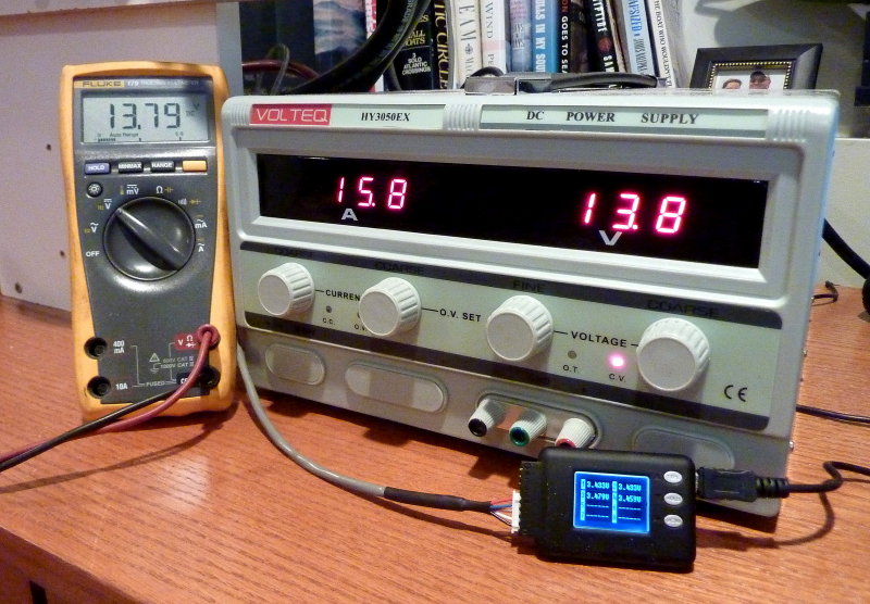
Knobs and Displays:
Left Digital Display = Current Output
Right Digital Display = Voltage
Red Light = Constant Voltage Mode (power supply is limiting voltage to 13.8V)
Left Knob = Current Control Dial
Second From left Knob = Over Voltage Limit
Third From Left Knob = Constant Voltage Fine Tune Adjustment
Right Knob = Constant Voltage Coarse Tune Adjustment
As you can see in this picture with 15A of current flowing the Mastech and the Fluke are in close agreement but I still trust my Fluke a lot more than the voltage display on the power supply.
TIP: When charging LFP cells or banks with a bench top power supply PLEASE dial the current back by about 20%. This will allow the power supply to run almost indefinitely and not cause undue wear and tear on the unit. I run my 30A model at 24A and my 50A model at 40A... I often parallel them and charge at 64A when doing cycle testing....
Nothing makes top balancing easier than a bench top power supply:
#1 Charge individual cells to .05V below max top balance voltage and allow current to taper
#2 Wire cells in parallel.
#3 Charge cells to max top balance voltage and let current go to next to nothing Winston = 3.65V / CALB = 3.6V etc.
#4 Done
Human Error Over Charge!
This cell and three others were over charged by one of the brightest guys in DIY LFP banks. He is also an EE. $hit happens and I use the $ for an S for a reason.
Quote:
"Charging 4 x 90Ah cells in parallel with a 40 amp 12v charger, thought I'd turned the charger off, didn't discover it till a few hrs later. The cell was at 4.55v from memory and so hot the terminal bolts burn into the finger tips. The strange smell of the electrolyte vapor, but no sign of any white cloud. The heat was similar to standing in front of an oil heater on full and was still quite noticeable the following morning. Only the 2 cells in the center bulged and they are the only two that failed. The cells at either end had better cooling, they bulged a bit, but they are still part of my battery bank 12 moths later."
Let's break this down to see how easy these mistakes can happen..
*These cells were in parallel which means a 3.2V nominal pack
*A 12V charger was used instead of a power supply or charger capable of LIMITING the voltage to 3.XX
*He thought he turned the charger off. This is a prime example of HEF (human error factor). No matter how smart we are, we are still capable of making human errors or being forgetful. This is just normal human nature.
*Cells hit 4.55VPC!!!!!!!!!!!!!!!!!!!!!!!!
*Cells DID NOT EXPLODE, Catch fire or do anything other than get very hot!
*The cells did not even smoke!
*Two of the four cells actually survived this abuse!
*Simply AMAZING!!!
*Imagine how long your cells will live if you don't allow HEF into the equation and you charge them PROPERLY for a fractional "C" system?
If an EE and guy who knows more than just about anyone I know on LFP, & the subject of fractional "C" use can do this, you could too. I will mention it again, use a BMS on your bank for HVC / LVC and a bench top power supply for top balancing...
So what actually happens when you do over charge? Over charge forces lithium oxide to form on the cathode. The LFP cathode is, well, lithium iron phosphate. By causing an over charge you have now converted some of the lithium iron phosphate to Lithium oxide, not good! There is no reconversion or fixing this situation and the cell is now irreversibly damaged. Even slight over charging episodes can cause increases in internal resistance and cause a loss of capacity.
With the CC/CV charging we use in the marine market, and multiple sources of it, your best and safest bet is to limit the constant voltage stage of charging to less than 14.2V or 3.55VPC (14.0V or 3.5VPC is even safer). Remember these cells are technically "full" at 3.4 VPC or 13.6V...
If your cells rest at room temperature for 3+ hours with no load and wind up at 3.4VPC they are full. Getting them full does require a voltage higher than 3.4VPC in order to get them to 3.4VPC rested, but not much higher. Charge to 13.8V or 14.0V and allow the current to tail off to about .025C (2.5A on a 100Ah cell) and your bank is now about as full as you'll need it to be.
I charge this 400Ah Winston pack to 13.8V and 0.025C current and it still delivers 425Ah's at a .25C load! This has now been tested and repeated eleven times in complete 100% discharge capacity test to confirm the Ah capacity...
Image Courtesy: Terry
15-NOV-2014
Choose A Location
The nice thing about LFP banks is their weight and size are both smaller and lighter than a comparable lead acid bank. Due to these differences in weight and size I was able to relocate the entire bank to a nice dry and higher area of the vessel. I reconfigured a storage area to take the battery bank and it fit like a glove.
Take the time to reconsider where your bank will be and don't just place it where the lead acid batteries were because there may be better alternatives.
Consider the following when choosing a location for a new LFP bank:
Weight Distribution
Moisture & Humidity
Corrosion Potential
Not In An Engine Space
Heat and Cold Potential
Access
17-APR-2013
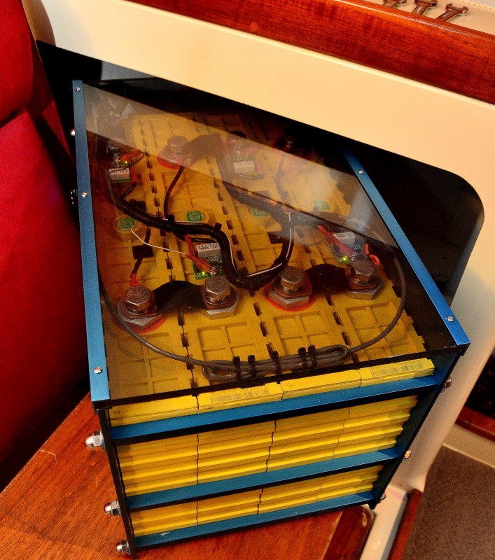
The Banks New Home
As can be seen the area chosen is high, dry and has good protection for the battery. Don't be afraid to get creative in where you install the bank, but do be safe..
10-APR-2013
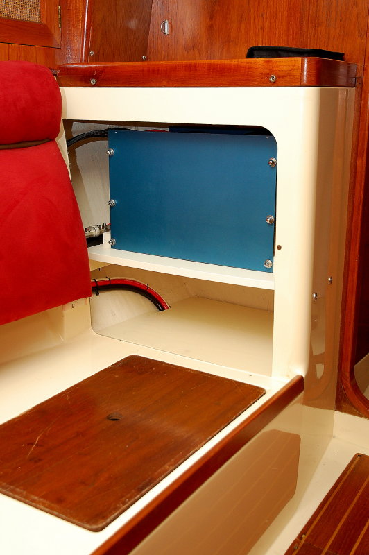
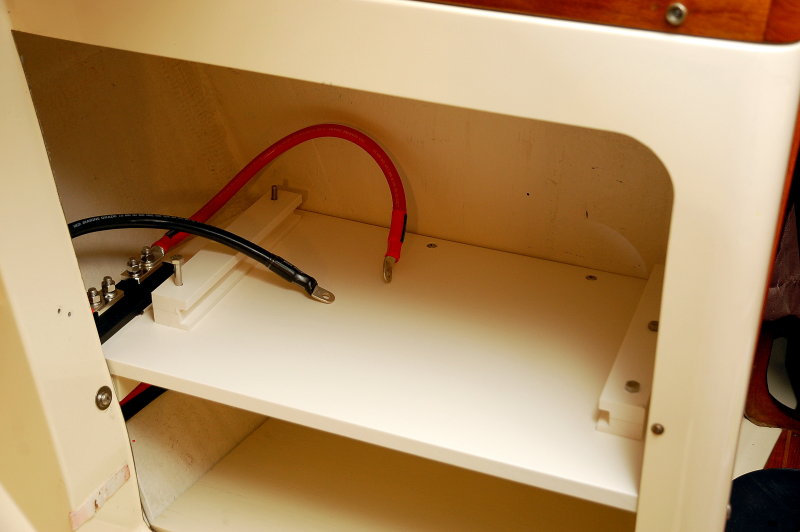
The Battery Compartment
Here's a shot of the empty battery compartment, simple, clean and with hold down clamps that do not allow for any movement of the installed battery. These banks have the ability to throw massive amounts of current into a dead short so where and how the battery is mounted is an important aspect of the installation.
10-APR-2013
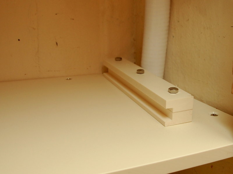
Make Sure The Battery Is Well Mounted
This clamp mechanism uses 3 X 3/8" bolts and two pieces of 3/4" thick HDPE board to clamp around the battery cases bottom draw bar. A slot was routed into each clamp at the perfect height to fit the battery case.
The battery case draw bars fit into the notches in the battery cells and compress the cells with 5/16" SS threaded rod. The square aluminum bars are 1/2" aluminum square tube which locks the cells in place and fits this hold down clamping mechanism. The battery can not move when installed.
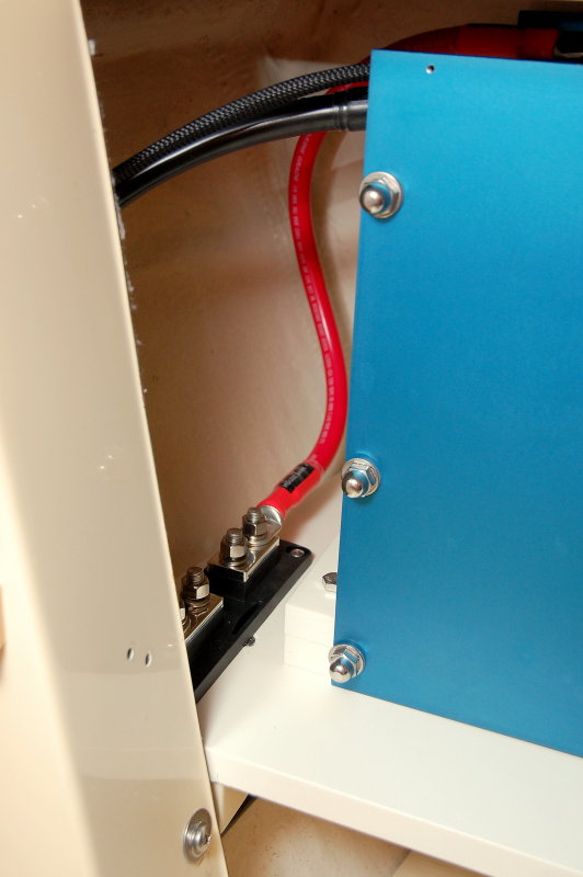
Over Current Protection
In this photo we can see the battery bank and the red 2/0 wire feeding the Class-T fuse holder. At a bare minimum you want to be using Class-T fuses as your main bank protection for an LFP bank. This bank can easily throw 20,000A or more of current into a dead short and can damage and literally blow windows out of ANL fuses. I had this happen during the testing of some ANL fuses sent to me by a DIY LFP guy from Cruisers Forum, Thanks Bob!!! Class-T fuses are fully metal encased and are a very safe fuse.
All fuses have what is called an AIC rating or amperage interrupt capacity rating. This is the rating at which the fuse will fail safely. Class-T Fuses have the highest AIC rating of any fuse we use in the marine environment. There are fuses out there with higher AIC ratings but none of them have fuse holders avaible that are suitable for a marine application.
Ideally the main bank over current protection needs to be within 7" of the battery bank but as we can see here that is often impossible. D'oh!!! There is technically more than 7" of wire to get from the + battery post to the Class-T fuse here. Is this an unsafe installation, hell no, but sometimes the standards are a little to broad brushed to apply realistically to the real world so we do the best we can...
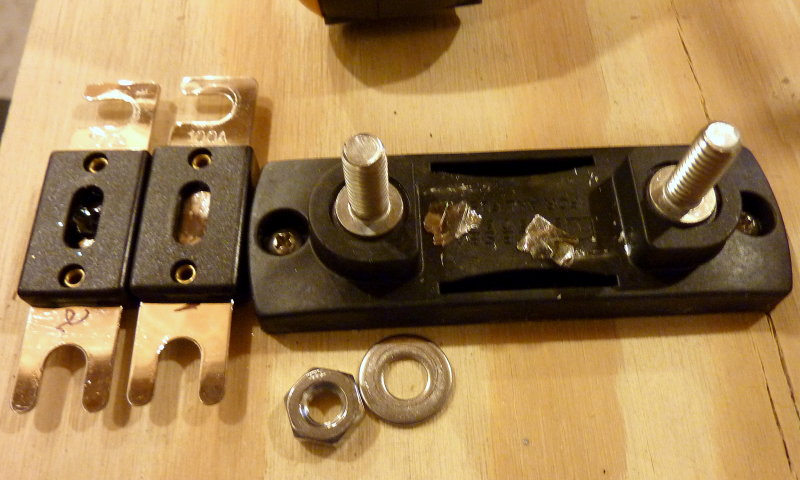
Unsafe ANL Fuse Failure
During the course of my testing & experimentation with LFP battery banks I blew approximately $400.00 worth of MRBF, ANL and Class-T fuses.
The only unsafe failures I had were off-brand elcheapo car stereo type ANL fuses. As can be seen here the windows literally exploded out of the fuse when it tripped. I did not have a single unsafe failure of a Cooper Bussmann/Blue Sea Ignition Protected ANL fuse but I only blew about 10 of them. I suppose if you blew 100 you may have an unsafe failure on an LFP bank..
Still, I would strongly urge Class-T as the bare minimum for LFP bank main overcurrent protection.
NOTE: Class T fuses do not have an ignition protection rating. As near as I can tell, from speaking with Blue Sea Systems as well as Cooper Bussmann, they have not been specifically tested for this. This only means that they've not been tested, not that they would necessarily be unsafe. Remember an ANL IP rated fuse has an AIC of 6000A and a Class-T non IP fuse has a 20,000A interrupt rating.. If you have a gasoline powered vessel, which requires ignition protected devices, consider this when engineering the over current protection for your LFP system..
Alternator Considerations For LiFePO4
If you decide on LFP then as I mentioned it is best designed as a system and a good alternator design and installation should always be part of that system.
Due to the extremely low internal resistance of these batteries, and the extremely flat voltage curve, LFP banks will tax an alternator to death if not properly installed. Because of the very low resistance the alternator will be in BULK mode for the vast majority of the charge cycle, (depends upon size) before even attaining absorption voltage.
With a high current alternator on lead acid, you can hit limiting/absorption voltage as low as 50% SOC where the alternator begins to catch a break.... You will not do this with an LFP, and your alternator will NOT get a break.
If you cycle the LFP bank to 80% DOD this means you are in BULK mode for approx 75% or more of the capacity of the entire bank bank before any sort of voltage limiting even begins..
BULK CHARGE means the alternator has not brought the terminal voltage of the battery bank up to ABSORPTION or the limiting voltage. In BULK the alternator is working FLAT OUT in what is referred to as CC or constant current mode... Once the bank comes up to ABSORPTION VOLTAGE we switch to CV or constant voltage mode where voltage is held steady and current begins to taper off based on what the battery can accept at that SOC and voltage.
In BULK / CC the alternators capacity/ability is your limit.
In ABSORPTION / CV the battery determines how much current can flow at a specific SOC and terminal voltage
Take a 400Ah LFP bank at 80% DOD and that is 320Ah's that need to go back in. With a 130A alt running hot at about 100A this means BULK will be about three hours! There is no alternator on the planet that can run at full bore for three straight hours, into an LFP bank, inside the typical engine room on a boat, unless perhaps the diode rack has been mounted externally with its own cooling fan. There is not a single small case alt that will survive this for long without a proper installation. NONE!!!
Let's say you're a marathon runner, and you can do the 26 miles at a pretty good jog. This is similar to a high capacity alternator feeding a large lead acid bank. You start out strong (BULK/CC) but as the race goes on you plateau & settle in at a sustainable pace (ABSORPTION/CV).
An alternator feeding an LFP bank is like trying to SPRINT the entire 26 mile marathon. Not going to happen....
FACTORY ALTERNATORS:
Some factory alternators have a built in temp compensation and it resides in the voltage regulator to reduce current / voltage as the alternator heats up. This really defeats the purpose of "charging fast" or even having an LFP bank if you want to capitalize on the fast & efficient charging LFP batteries can offer.. While this alternator temp compensation feature is self protective of the alternator it is really a very poor regulation choice for an LFP bank. I have seen Hitachi alternators so hot they have reduced the voltage output to 13.2V. Considering the resting voltage of an LFP bank is higher that, well..... Do it right and build this as a "system"..
High Performance Alternators:
With LFP you must ignore the bovine dung ratings manufacturers suggest. Kost "high performance" alternators are rated based on stator/rotor specification/design size. They are NOT rated for continuous duty at full output! What? Bottom line is DO NOT EVER expect the "rated output" from your high performance marine alternator for more than a few minutes. Depending upon the specific alternator plan to reduce your actual constant duty output by as much as 20-50% or more.
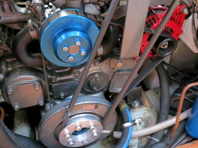
PHOTO:
Here we are looking at a Yanmar four cylinder engine with a Balmar / Alt Mount serpentine conversion and a Balmar AT series 165A alternator. The Balmar AT series is a hairpin wound small case alternator. This stator / rotor design is relatively new technology for the marine market and allows extremely high performance out of a small case alternator.
Currently the Balmar AT series are the meanest, bad a$$ small case alternators you can buy, performance wise, but they are still a small case alt and LFP can still over-tax them and burn them up if they not set up correctly.. I used the $$ signs in the word ass for a reason, they are not inexpensive...
Another great option, if you are locked into a small case alternator, is to let
Mark Grasser DC Power Solutions (LINK) build you a remotely rectified small case alternator. This is what I run on my own vessel and Mark is a great guy to deal with.
Unfortunately many sailboats don't have the room for a massive large case alternator with external bracket etc. If you do, that is great, and I would steer you in that direction if not Mark Grasser or a Balmar AT series would be the best direction to go.
Does this mean other small case high performance alternators can't be used on LFP? Absolutely not, it just means the percentage of "rated output" you get out of the alternator will be less than it is on an AT series and it will need to be dialed back in the regulator settings further than an AT series will. While the AT is a great little alternator it is not immune to being cooked from improper set up and installation.
With a remotely rectified Mark Grasser alternator the remote rectifier removes a lot of heat from the alternator and allows it to run significantly cooler with higher continuous outputs. On my own vessel I do not use current limiting and the alternator has never been hotter 227 degrees. The same alternator before I converted it to remote rectification could easily exceed 275 degrees and alternator, before I converted it, required belt manager level 4 in terms of current limiting.
Large Frame Alternator
When space allows, a large frame/case alternator is going to be better suited to LFP banks. They will still need some current limiting/derating & temp protection but they are purposely designed from the ground up, and intended for, driving large loads.
Small case alternators are adapted and modified for driving large loads for longer duration's but large case alternators were specifically designed for this type of duty from the ground up. Small case alternators will require more current limiting/derating to survive LFP banks than will most heavy duty large case alternators.
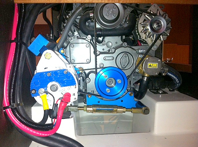
PHOTO: In this photo we have a large case alternator on a Balmar/AltMount custom bracket driven by a serpentine/rib belt. If you have the room, this is perhaps the best option to go with for charging LFP banks..
Image Courtesy C. Kelley
Alternator Drive Belts
In order to get current out of an alternator this requires a considerable amount of work on the part of an alternator belt. If designing the system for LFP there is no better option I know of than a multi-rib or serpentine belt kit for your alternator. I suppose you could design a geared PTO system but $$$$$...
A single serpentine belt is capable of driving 190A - 200A of current with less heat, less belt tension and less strain on water pump or alternator bearings.
NOTE: Universal & Westerbeke suggest the largest alternator they want to see on their engines is 190A. Yanmar has no such advisory that I have been able to find. With proper regulation you can run a 225A + alternator current limited to 190A, and do this all day long.
#1 Choice = Serpentine / Multi-Rib (Balmar, Mark Grasser DC Solutions or ElectroMaax)
#2 Choice = Dual belt configuration. This is a very distant second choice. Dual belt kits rarely if ever work as intended or share the load equally among belts. On an LFP bank they can become a belt dust nightmare. Matched pairs of belts are also getting extremely tough to find because even industry has moved away from v-belts. You will have belt dust issues with a dual-pulley/belt configuration driving LFP. Unless you already have dual belts, spend your money on a serpentine kit.
#3 Choice = 1/2" Single V-Belt - A single 1/2" v-belt driving LFP should be limited to approx 80A of current. I do not advise charging LFP with a single v-belt.
#4 Choice = 3/8" Single V-Belt - A single 3/8" v-belt driving LFP should be limited to approx 60A of current. I do not advise charging LFP with a single v-belt.
NOTE: I am ignoring common wisdom that a single 1/2" belt can drive 100A and a 3/8" belt can drive 80A. This is all well and good with lead acid but not for 3+ hours at full bore with LFP. The same goes for large banks of AGM or GEL with a small alternator...
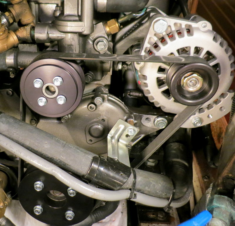
PHOTO: An ElectroMaax serpentine pulley kit and a Mark Grasser DC Solutions Premier Series 140A alternator.