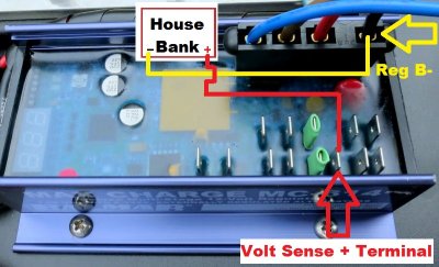
These are the actual terminals used by the Balmar MC-614 regulator to make the voltage sensing circuit work. It requires both the regulator B- terminal and the + volt sense terminal to get accurate voltage sensing.
One minor point. Looks like yellow arrow is pointing to black wire which is the negative supply to the regulator. So that black wire carries supply current for the regulator and is subject to voltage drop as a result of current needed to power regulator circuitry, all those ICs buried in flex epoxy. This is different from sense + terminal which is clearly not carrying supply current to regulator IC circuitry. You have the red wire on the 4 terminal connector which supplies the current. I am about to wire the same regulator, I also have balmar 9115. So i am wondering what voltage drop do you see on that black wire from battery negative terminal to the point indicated by yellow arrow. Pretty much the ends you drew with yellow line.
wsmurdoch
15-Apr-2015 01:40
My Xantrex XAR regulator has two black wires; one on the four wire connector and one on a separate spade on the regulator which the instruction manual calls the "independent ground terminal". The instructions actually say, "Connect the two BLACK ground wires at the preferred ground at the rear of the alternator (see Figure 2 for typical alternator ground connection)". Should one, the other, or both of these black wires be connected to the battery negative terminal? What is the difference between them?