


|
|
|
|
|
|
| |
| 10-JAN-2012 | |
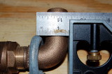
If you look at the video you'll see where the "load" was applied to the elbow which is a full 1 3/8" inward of where the ABYC load is to be applied at the "innermost" portion of the assembly. Here I am measuring the load contact point from the "innermost" portion of the assembly.
I just don't have a good way to apply the load to the "innermost" portion of a male hose adapter so used an elbow instead. In the process I gave up 1 3/8" of "lever" which actually favors the seacock when testing to ABYC H-27 standards. Despite this 1 3/8" of favorable advantage for the seacock assembly, the thru-hull still failed at 404 pounds and never got close to 500 pounds for 30 seconds.
A straight male hose adapter is even taller than the elbow and would thus provide for more lever and move "innermost" even further away from the hull.
© All Images property of Compass Marine Inc.