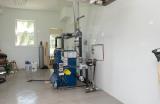
Closer view of boiler. Supply is taken from 3" tee (upstream of reducing nipple connected to equalizer - with bushings and 1" nipples and valve in photo). Return is to 2" tee at bottom right (adacent to feed water inlet). When heat is demanded damper motor runs until damper is open. Open damper closes circuit to power venter which starts to run. When pressure sensor in flue detects negative flue pressure cirucuit to gas contol is closed through fill level sensor (black box on front of boiler), Pressuretrol (small gray box on front of boiler visible in next picture), rollout and spill switches which opens pilot gas valve and starts spark. When gas controler detects pilot flame current main gas valve is opened. Pressuretrol opens when upper set pressure is reached shutting off gas and commanding damper to close (unless set to always open mode - in either case signal to power venter is removed). Power venter keeps running for 30 sec on timer and then shuts down thus completing cycle. Auto feeder (black box behind boiler near wall) supplies additional water as required to satisfy low water probe.