In this picture I have mounted the charger to a back board which will get mounted to the boat. The wires are affixed to the board with sufficient strain relief to prevent inadvertent loading of the attachment point to the charger. The ends of the wires are crimped with ring terminals using the proper tool and then sealed with adhesive lined heat shrink. I also coat the lugs with a terminal grease to prevent oxidation/corrosion at the lug/terminal strip interface.
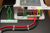
One of the more critical aspects of charger installations, that I nearly always see violated, is the green case/chassis ground wire shown. If I had to guess I would say that nearly 85% of the installations I see are either not case grounded or the case ground wire is to small.
This green grounding wire grounds the chargers metal frame to the vessel and allows your over current protection devices to work properly, if there is an internal fault that shorts to the case.
Chargers and inverter/chargers are equipped with grounding connections for both the AC
side and DC side of the device. Proper Earthing is there to prevent shocks from the AC side, and to minimize or prevent fire hazard from DC side.
About eight times out of ten the AC Earth connection is the only one I see being used. So, what if there were a fault in the DC side of the system? Can the AC ground wire handle that? The answer to that question is almost always a resounding NO!
A fault in the DC side can supply enough current to overwhelm and overheat the AC green grounding wire. It can even do this well before tripping a fuse or breaker. It is a must do requirement that the case be bonded/grounded/Earthed with a green wire of not less than one size smaller than the DC conductors!!
This green wire gets sized for the DC side of the charger. The green AC ground will not satisfy the ABYC case ground requirement on an AC/DC battery charger. Follow me on this one. If there is a fault on the DC side of the charger the AC green wires size may not be able to handle this fault and could be undersized in having to handle that fault. This is why the requirement for the chargers case ground is for no less than one size smaller than the DC output wires.
The ABYC standard suggests that the case ground for chargers needs to be no less than one AWG gauge size smaller than the DC output wires. So, if you have 6 GA DC wire then you need no less than an 8 GA case ground wire. Even if your wire is already technically "over sized" your surveyor or insurance company may not know this so it is always best to wire it equal to or no less than one AWG size less than the DC output wires.
This green wire is routed from the charger to the ships DC ground buss which normally is earthed or grounded to the engine block..