


|
|
|
|
|
|
| George&Arlene | profile | all galleries >> Galleries >> ASU Flight Simulator Visit March 2014 | tree view | thumbnails | slideshow |
| previous page | pages 1 2 3 4 5 ALL | next page |
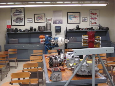 IMG_3915.JPG |
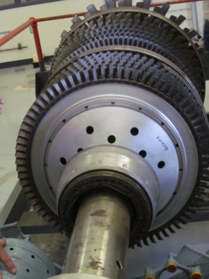
 IMG_3917.JPG Another room with even more aircraft powwer plants. |
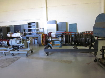 IMG_3918.JPG |
 IMG_3919.JPG This display shows how a de-icing system works. The wing leading edge (vertical object at far left) has a black 'rubber' covering. When pressurized, it expands and breaks up the accumulated ice coating. |
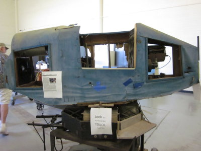 IMG_3920.JPG One of the well-known Link trainers. Invented in the 1930s and widely used for pilot training during WW2. It doesn't look in real good shape. |
 IMG_3921.JPG If you can't read it, here is the URL for the same sheet.
|
 IMG_3922.JPG I remember this was an Auxiliary Power Unit (APU); obviously from a larger plane. |
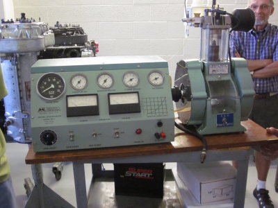 IMG_3923.JPG This is clever. A single cylinder gasoline engine with a glass/plastic transparent cylinder. |
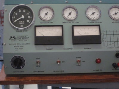 IMG_3924.JPG The fuel and air mixture can be adjusted and the effect on the flame color, and engine parameter can be observed. They started it up and got it up to 1500 rpm. |
 IMG_3925.JPG |
 IMG_3926.JPG |
 IMG_3927.JPG The yellow portion shows how the jet fuel is introduced, mixed with the compressed air and ignited. This design isn't used any more. |
| previous page | pages 1 2 3 4 5 ALL | next page |