


|
|
|
|
|
|
| fred harmon | profile | all galleries >> concours14 >> powercommander | tree view | thumbnails | slideshow |
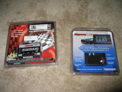 PowerCommander and LCD display |
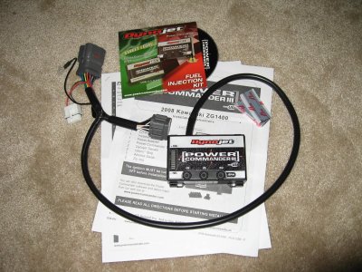 In the box is the Power Commander unit, and harness and instructions (with pictures) and software for your PC |
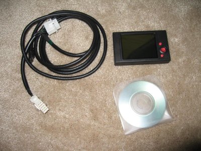 The LCD unit comes with a harness to connect to the Power Commander and a software disc that has the instructions |
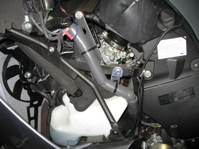 First you have to remove the left side fairing panel and inner panel |
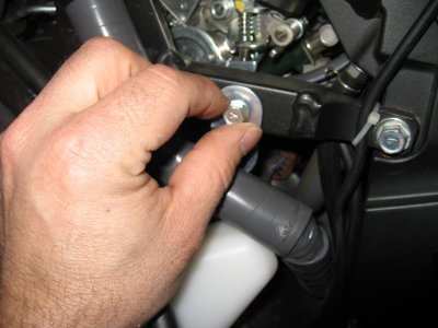 Next remove the bolt that hold the wire harness support |
 Removing top bolt on coolant reservoir |
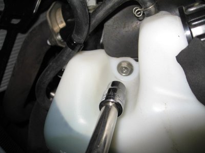
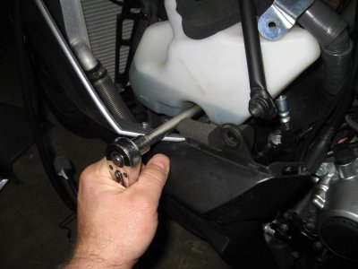 Removing bottom bolt on coolant tank |
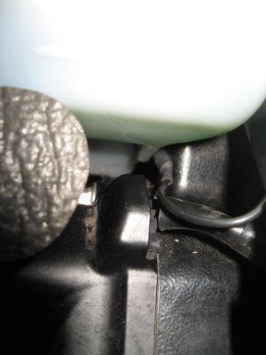
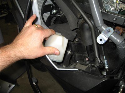 Push the coolant reservoir out of your way |
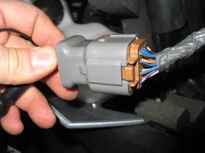
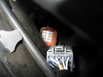
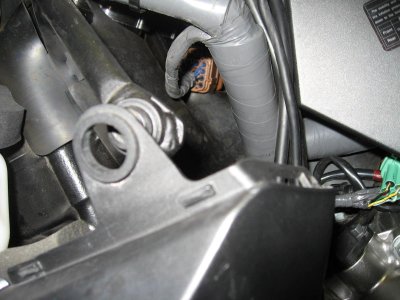 Here you can see the connector you need to access |
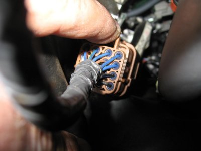 Push down on the tab to pull out the conntector |
 This shows the locking tab on the top of the connector |
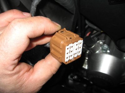
 The gray power commander connects to the bike side connectors |
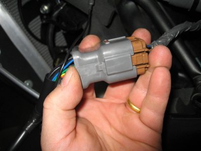
 Power Commander connector plugged in |
 Next you need to connect the other connectors together |
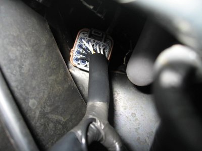 Connectors locked into place. Make sure you hear them click positive into position |
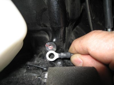 The ground wire can be mounted where the bottom bolt for the coolant tank goes |
 With coolant reservoir in position, note ground wire position |
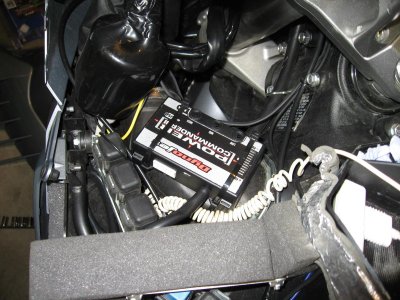 I located the Power Commander unit on top of the ram air hose and zip tied it in place |
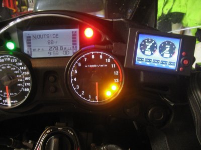
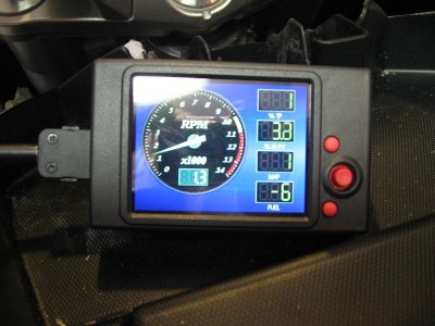 LCD unit powered on |
 LCD uses a touch panel screen that works well and makes changing maps a piece of cake |
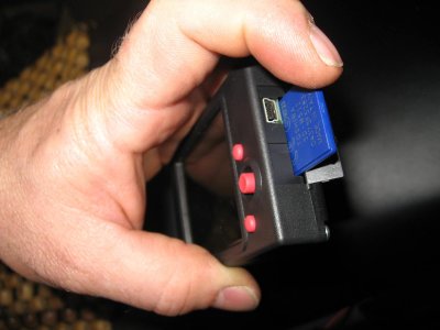 The LCD unit accepts SD memory cards to store maps on |
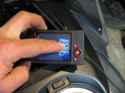
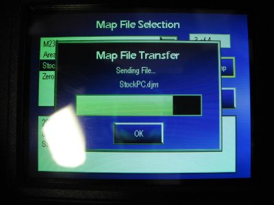 Loading a map on the fly using the LCD unit |
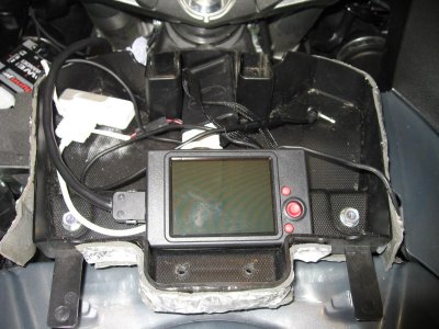 The LCD unit fits in the glove box |
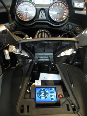 LCD unit access from glovebox |
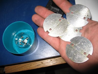 Left over parts |
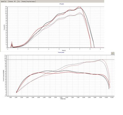
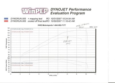 Dyno1.JPG |
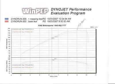 Dyno2.JPG |
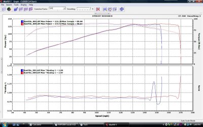 2010 C14 Before and After Dyno.jpg |
 GtechPro run #1 (with modified ECU) |
 LCD_Display_Butterflys 004a.JPG |
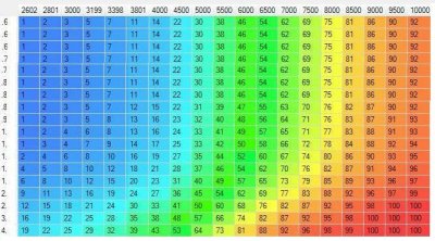 2010 C14 SecondaryThrottleMapA1a.JPG |
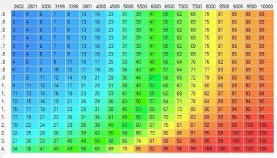 2010 C14 SecondaryThrottleMapB1b.JPG |
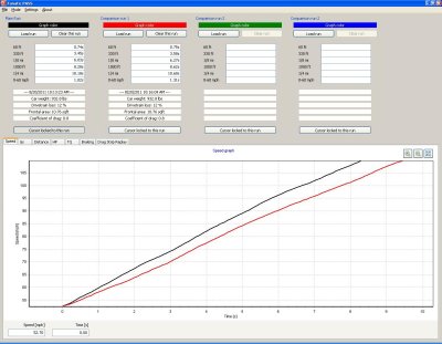 4th Gear Roll On with Guhl mode, versus OEM Economy mode |
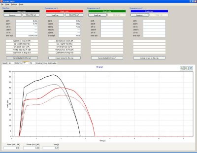 5th Gear Roll On with Guhl mode, versus OEM Economy mode |
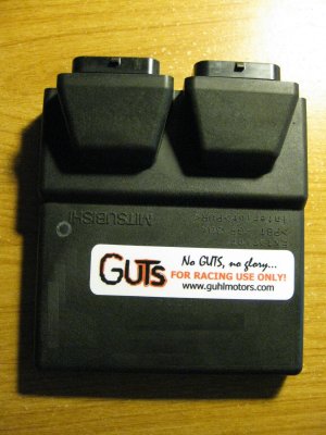 GuhlFlash 002a.JPG |