


|
|
|
|
|
|
| fred harmon | profile | all galleries >> Galleries >> G Force Alarm System | tree view | thumbnails | slideshow |
| previous page | pages 1 2 3 ALL | next page |
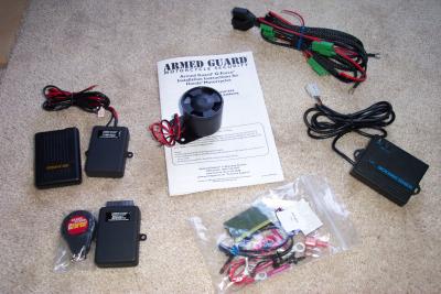 Here the kit, including pager, and perimeter options. MSRP $224.95 Distributed by Big Bike Parts and Electrical Connection |
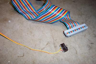
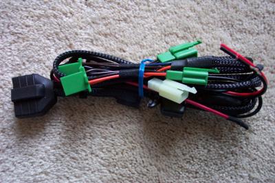 This is the wire harness to plug the G Force directly into the GL1800 with no splicing needed |
 The large connector is for the alarm, and smaller connectors for starter and rear turn signal lights |
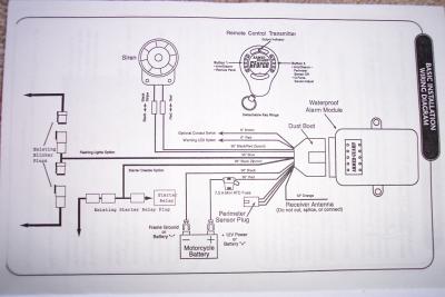 Connection Diagram shows how the system connects to the bike. |
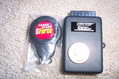 This is the alarm brain and remote |
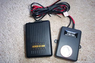 The pager option, which costs an additional $125. Range is up to 1 mile |
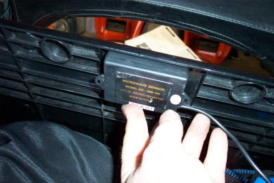
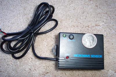 Microwave perimeter sensor option, $45 adjustable range to 10'. Selectable on/off feature with remote transmitter |
 Armed Guard point of contact |
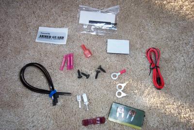 Supplied hardware for installation |
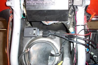
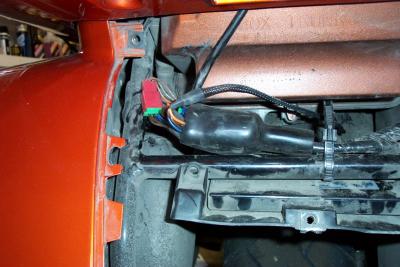
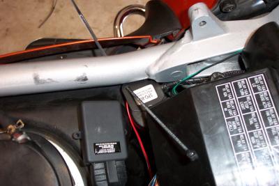
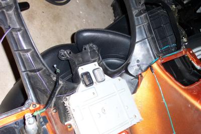
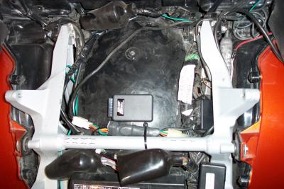 This is one possible mounting location. Due to my Mic-Mutes and Kennedy PTT hack, I moved it to a less crowded spot |
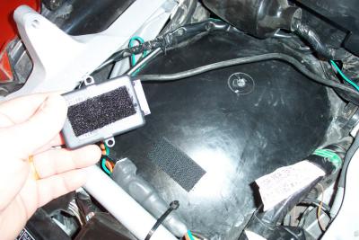 You can either Velcro or screw it in place |
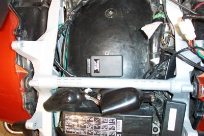 If you don't have Mic-Mutes, the unit will mount nicely agains the crossover support bar |
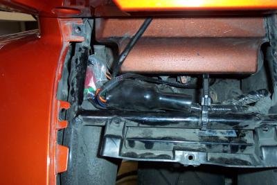
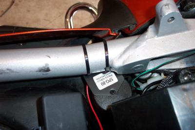
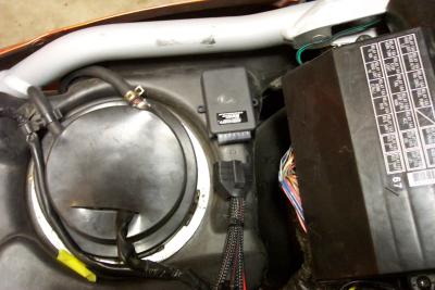 I found a less crowded space on top of the gas tank. If you mount it here DO NOT screw it into the gas tank |
 I used Velcro to hold it to the tank. DO NOT USE SCREWS INTO YOUR GAS TANK UNLESS YOU WANT A GAS LEAK |
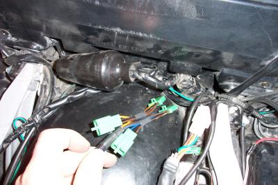
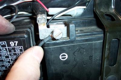
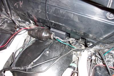
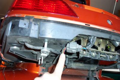
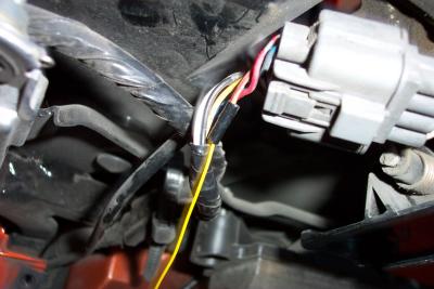
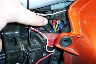 The starter connector is next to the battery. It is a red connector with a Green/Red stripe and a Yellow/Red stripe wire |
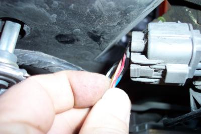
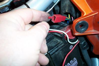 Here is the starter connector disconnected |
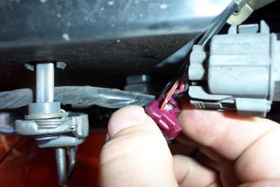
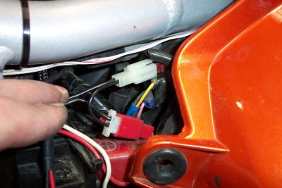 The alarm connectors plug into the starter connector in series |
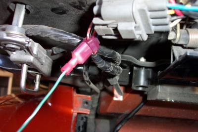
 I tucked all the connectors back into the boot to give them some weather protection |
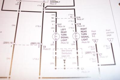 This is page 9-4 of the ETM. We need to locate connectors C17 and C18 |
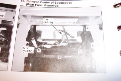 Photo 54 on page 12-8 of the ETM shows connector locations. |
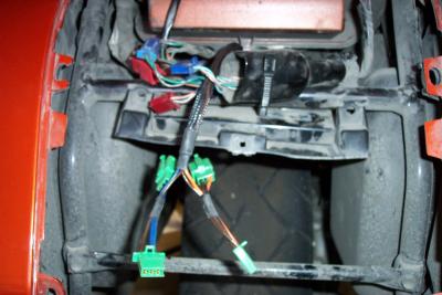
 You have to pull of the rear panel to reach the rear turn signal connectors |
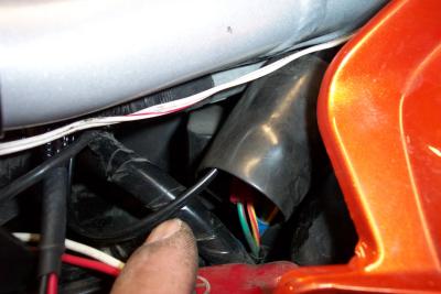
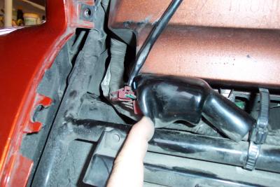 The connectors are inside this rubber boot |
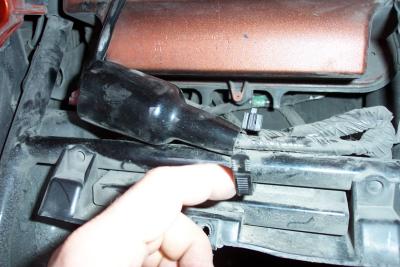 Release the zip tie so you can pull the boot back out of the way |
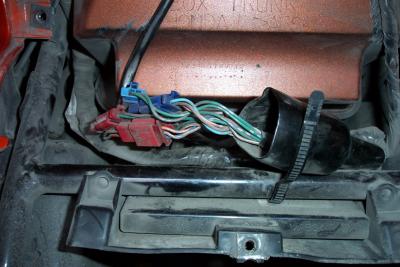 Connectors exposed |
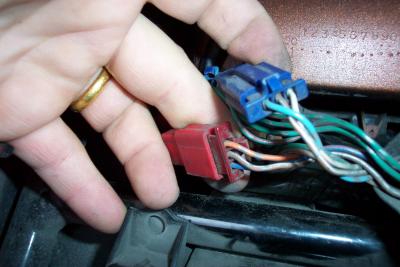 The two connectors we are after have three wires each |
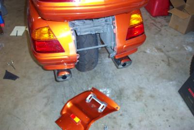
 Now you have to fish the harness down under the trunk, between the rear fender |
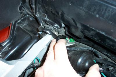 There is a hole on the right rear side of the trunk you can fish the harness through |
 Pull the harness through back to the turn signal connectors |
 Then just connect each set in series |
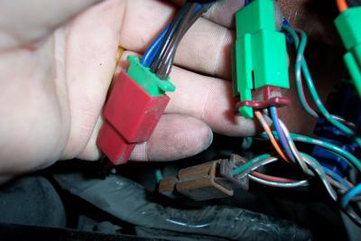 Second set connected in series |
 All connections done for rear turn signals |
 Now you have to stuff it all back into the boot. One connector wouldn't fit |
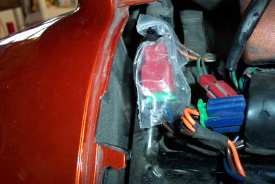 I wraped the loose connector in a small ziplock bag and tied the top closed |
 All connectors are now protected from the water spray of the rear wheel |
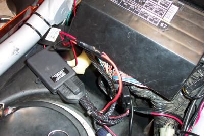
 Here is the negative battery connection. Do the same for the positive side |
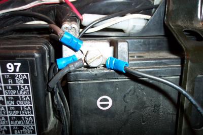 Here is what my negative battery connection really looks like with all my other toys hooked up |
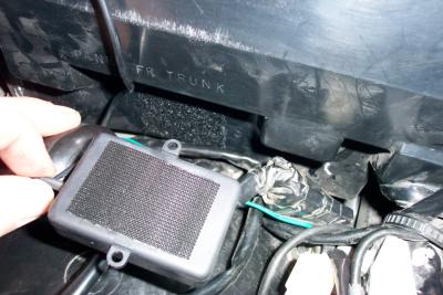
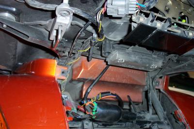
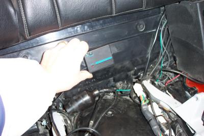 One possible location of Microwave motion sensor |
 Instead, I decided to mount it INSIDE the trunk, facing forward. This position gives good response at the minimuim setting |
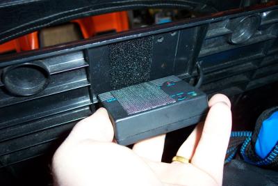 Again, I used Velcro to hold it in place |
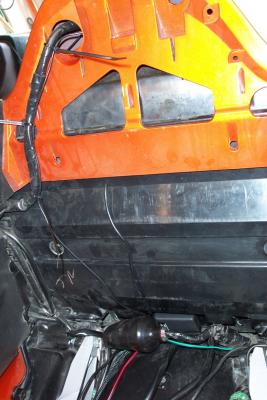
 I put the siren facing down underneath the right side frame rail, between the gas tank and rear fender |
 I used two zip ties to attach it to the frame rail |
 Here I used Velco on the Pager module (I just love Velcro) |
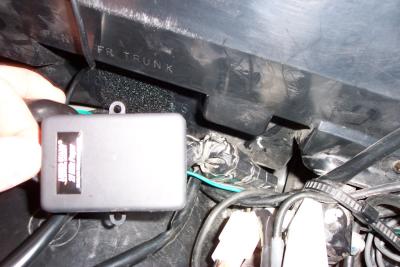 Locating pager module |
 Pager Module in position |
 I removed the passengar back rest (2 screws) and ran the pager antenna wire up into the top of the trunk for good transmission |
 Here are the alarm and pager wires connected. I choose to solder and heat shrink them |
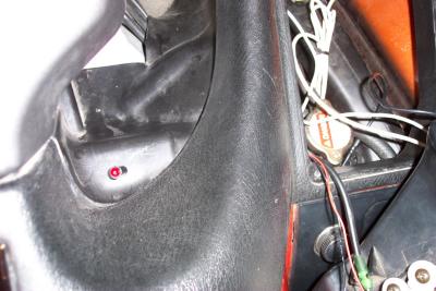
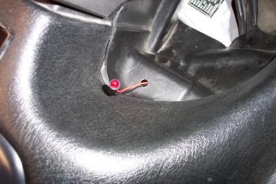 Location of flashing diode next to ignition on right side |
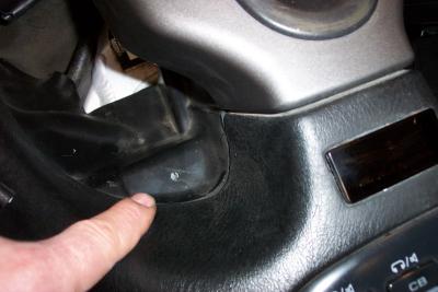 Don't try to mount it on the left side like I did. There is something underneath the cover here that will block it. |
 I routed the wires over to the right side glove box |
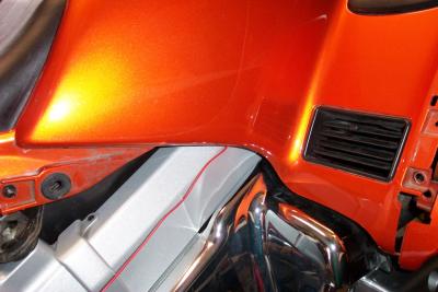 I then loosened one side of the top shelter and routed the red wire down. The black I connected to a ground point on the bike |
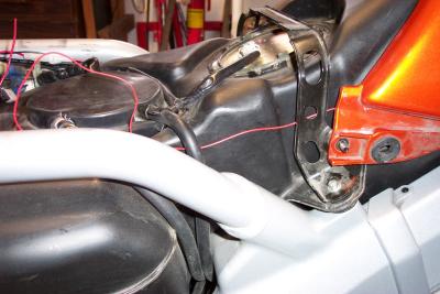 I ran the red wire back along the tank back to the alarm box |
 Alarm installation complete |
 Remove the lower trunk panel to access the trunk switch sense wire in connector C16 |
 The wire you need to attach to is the brown wire with a red stripe (see page 11-1 of the ETM) |
 You can attach a piggy back connector to this wire and no splicing will be needed |
 Piggyback connector in place |
 Or, you can solder and heat shrink the new wire to the existing brown/red wire as I did |
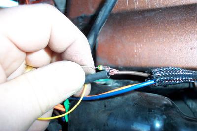 The other end of your new wire needs to be attached to a diode, and then connected to the brown wire in the alarm harness |
 Wire in place and connected to alarm and trunk sense switch |
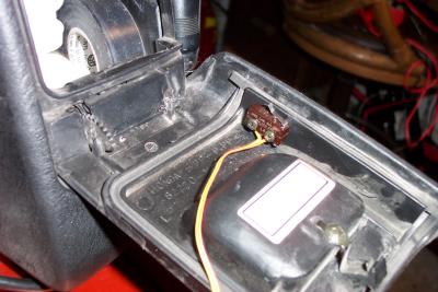
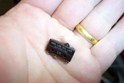 Here is a micro-switch I used to make a sense switch for the rear gloveboxes. You could also use a magnetic switch |
 I soldered two strands of ribbon cable to the normally closed switch contacts |
 One option is to attach the switch to the sides of the door. |
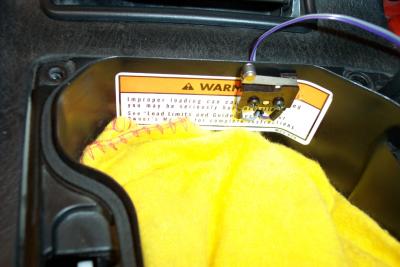
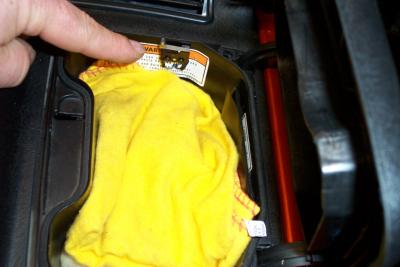
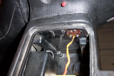 I decided to install it with the switch attached to the top edge of the glove box |
 Here is the switch fully installed |
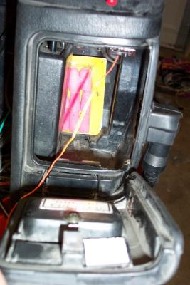
 I also installed micro-switches in both front gloveboxes. |
 I made a small hole and ran the wires out the back of the glovebox and through a small 2 pin connector |
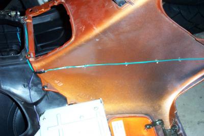 I removed the top shelter and routed the wires down the inside of it, tacking them in place with some hot melt glue |
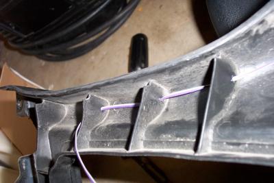 I melted holes in the bottom of the top shelter guides with a hot nail and routed the wires through to hold them in place |
 Completed wire installation. All 4 switch wires then go to ground on one side and to brown wire in alarm harness on other side |
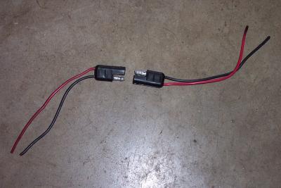 Here are the Radio Shack power connectors I use on the bike |
| previous page | pages 1 2 3 ALL | next page |