


|
|
|
|
|
|
| fred harmon | profile | all galleries >> Galleries >> antidive | tree view | thumbnails | slideshow |
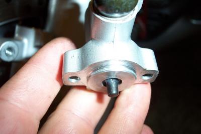
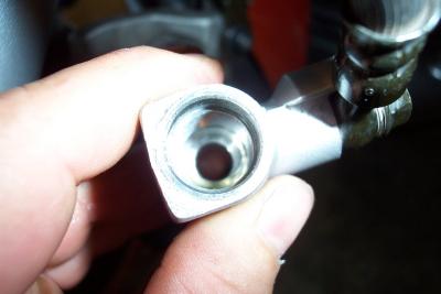
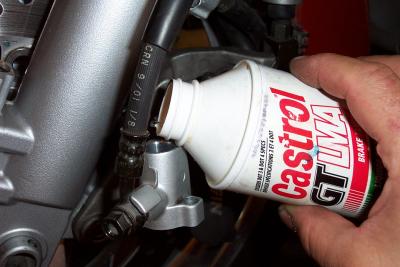
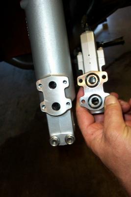 Here is the valve body remove from the fork leg, with fork oil all drained out |
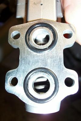 Here is a glimpse inside the valve |
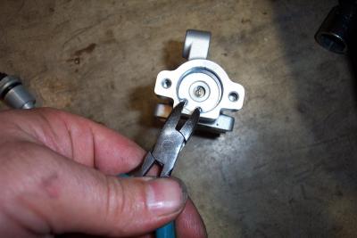
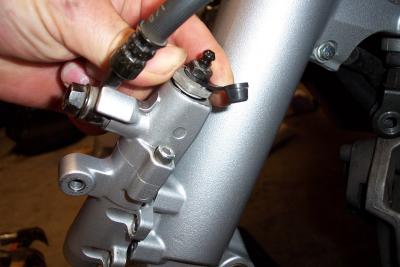 Here I am removing the top bleeder mount so I can then remove the upper piston |
 Top bleeder assy comes off with a 19mm socket |
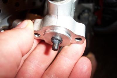
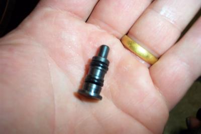
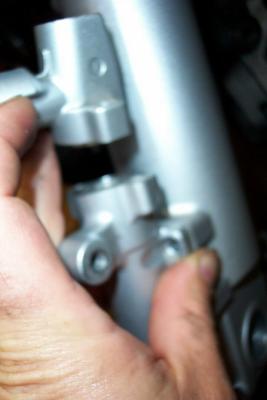
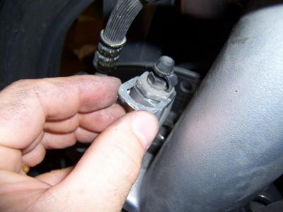
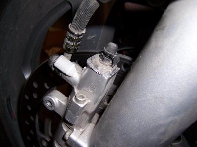
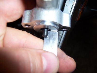
 Here is a look at the actuator. This is in the off position |
 By pushing up on the left brake caliper, you should see the actuator come out as shown here if it is working properly |
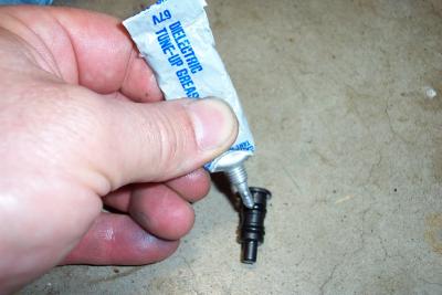
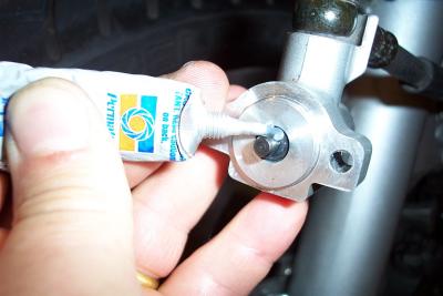 The manual advises you to lubricate this actuator. I used silicone grease |
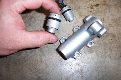
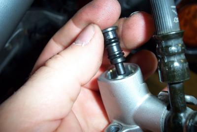 Here is the actuator removed from the upper section of the valve body |
 Carfully inspect the O rings. Some have been found to be cut |
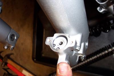
 Here is a look inside the upper section of the valve body |
 This is looking in from the bottom of the lower section with the piston removed |
 I lubricated the O rings with silicone grease before re-installation |
 Once the valve is back together, if you fill the top with brake fluid before you re-install the bleeder, it will bleed easier |
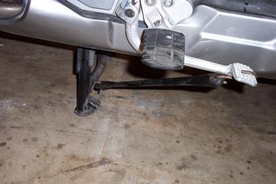 Home made third hand for helping bleed rear brake system |
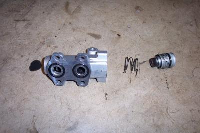
 Here I am seperating the halves of the valve to look at the lower section |
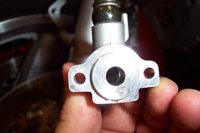
 This is the top of the lower section of the valve |
 You have to remove the snap ring to remove the lower piston |
 Here is the lower piston removed. There is a spring underneath it. |
 Here is a look at the lower piston. Brake bleeder for the top section shown in background. |
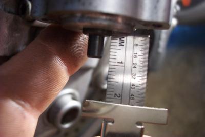
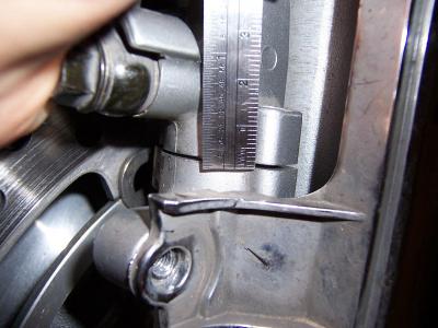
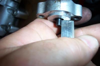 Valve fully retracted, protudes 6mm |
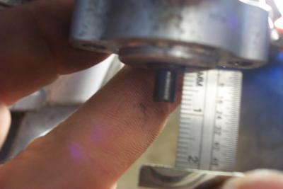
 Valve fully extended protrudes 9 mm |
 When released, valve only retracts 1mm due to tight O rings |
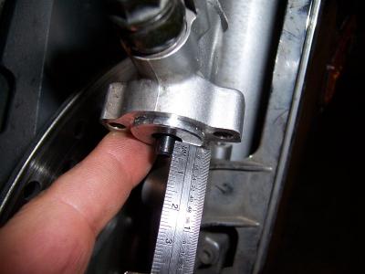
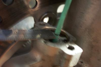 Measuring the resting point of lower valve |
 Lower valve resting point is about 9mm |
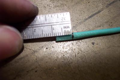
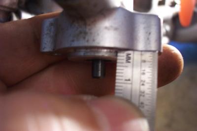 Add 2 mm for the lip on the edge of the valve body |
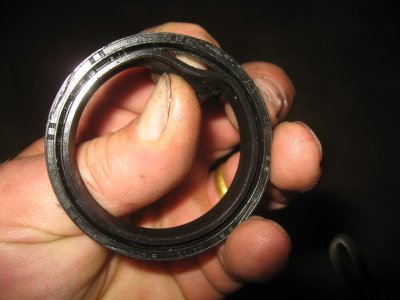
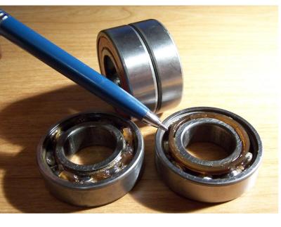 Front wheel bearings. Note they are two bearings stuck together by a plastic ring |
 The number printed on the bearing is 6004LU |
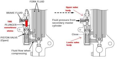 anti-dive valve diagram |
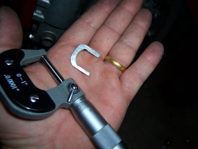 .035 inch shim for anti dive |
 Shim is installed under bleeder valve assy |
 Shim in place |
 Normally there is a 1mm gap between the halves when the upper valve is retracted |
 Upper valve normal resting point shows about 6mm protruding |
 With shim in place, upper valve now only protrudes 5mm |
 With shim in place, no gap occurs and upper and lower valves are just barely contacting |
 BlownSeal 006.JPG |