


|
|
|
|
|
|
| |
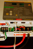
In this photo I have plugged in the temp sensor and am testing the charger to see if it recognizes the temp sensor. It did. With the Sterling Remote Panel the charger will tell you the battery, charger and transformer temp to within 1 degree. A pretty cool feature.
The AC wiring should be sized based on the manual for your charger. For this charger it calls for 14/3 AWG AC colored wire. The input for the AC wiring is marked L - N - G or BLACK/HOT, NEUTRAL/WHITE & GREEN/EARTHING GROUND.
Your charger should ideally have it's own dedicated breaker in the AC panel sized to protect the AC wire you're using. It is not suggested to share a breaker with any other device for a fixed mounted charger. This one uses a 15A breaker and 14/3 AWG AC color coded wire.
Always install your AC & DC wiring to acceptable color code standards. For AC and a single phase charger like this it is:
AC WIRING:
Black = HOT
White = NEUTRAL
Green = GROUNDING/EARTH
DC WIRING:
Red = POSITIVE
Black or Yellow = NEGATIVE
Green = BONDING or EARTHING
It is not advised to run AC & DC wires together in the same bundle unless sheathed separately. Try to keep your AC/DC wiring runs separate or sheath the AC wires to keep them isolated from the DC wiring.
© All Images property of Compass Marine Inc.